Threaded parts & spacers
Define thread type, engagement, shoulder length, mating faces and deburring. Review inspection of the features that locate the assembly.
ENGINEERING EXAMPLES
Examples in 5-axis machining, turning, mold making and metal 3D printing. Each one describes the component, the manufacturing route and the inspection plan.
Request a Quote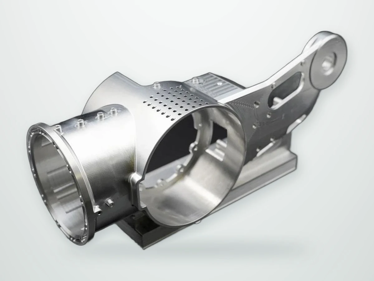
5-AXIS CNC
Coaxial bearing bores and angled passages in 7075-T6.
View the example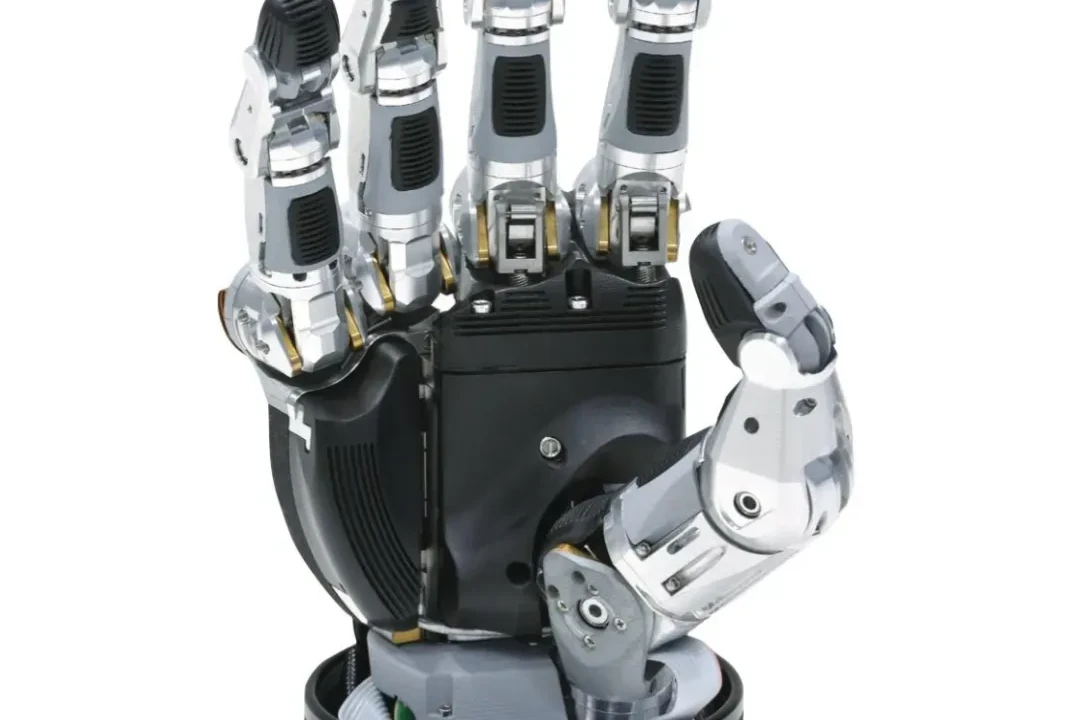
5-AXIS CNC
Finger links, joint supports and mounting interfaces; review pivot fits and assembly clearance.
View the example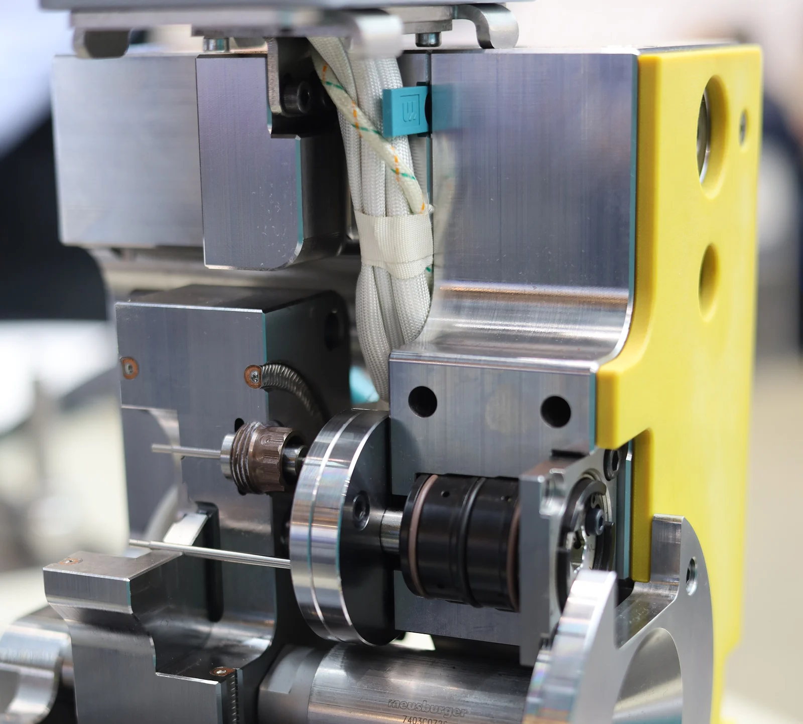
MOLD & MOLDING
Clear polycarbonate threaded caps released by a rotating core.
View the exampleMETAL 3D PRINTING
AlSi10Mg printed, stress relieved and CNC-finished on sealing faces.
View the example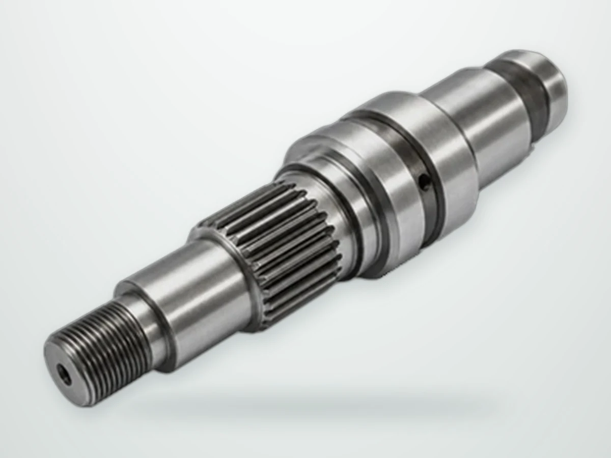
TURNING & GRINDING
Bearing journals held to ±0.005 mm with runout of 0.01 mm.
View the example
MILLING & WIRE EDM
Pin positions within ±0.01 mm across every fixture in the set.
View the example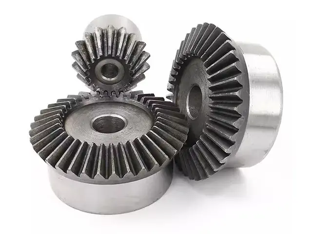
GEARS & SHAFTS
Matched straight bevel pairs for 90 degree drives in 42CrMo4.
View the example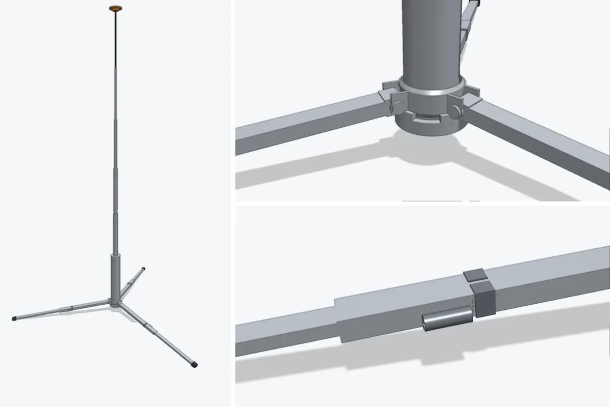
ASSEMBLY
Folds into a 140 × 35 mm envelope and extends to 610 mm, with a welded stainless body and three folding legs.
View the example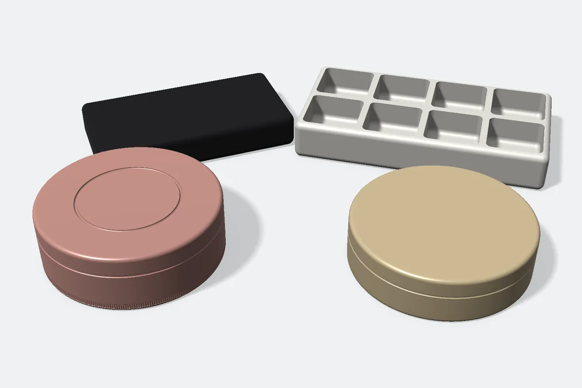
CNC & ANODIZING
Four 6061-T6 products in rose gold, champagne, matte black and pearl white, with sealed lids and magnets.
View the exampleEngineering considerations we review for the most common part families we manufacture.

Pockets, bores and mounting faces locate internal assemblies. Review wall thickness, cutter access, internal radii and sealing or bearing interfaces.
Inspection priorities: Bore position, mounting datums, flatness and finish masking. A displaced bore or coated mating face can prevent assembly.
Read the engineering notes
Stepped diameters, shoulders, grooves and threads are coordinated around coaxial features. Secondary flats and cross-holes may require milling or drilling.
Inspection priorities: Mating fits, datum references, runout, roughness and threads. Poor coaxial control can increase drag or affect rotating alignment.
Read the engineering notes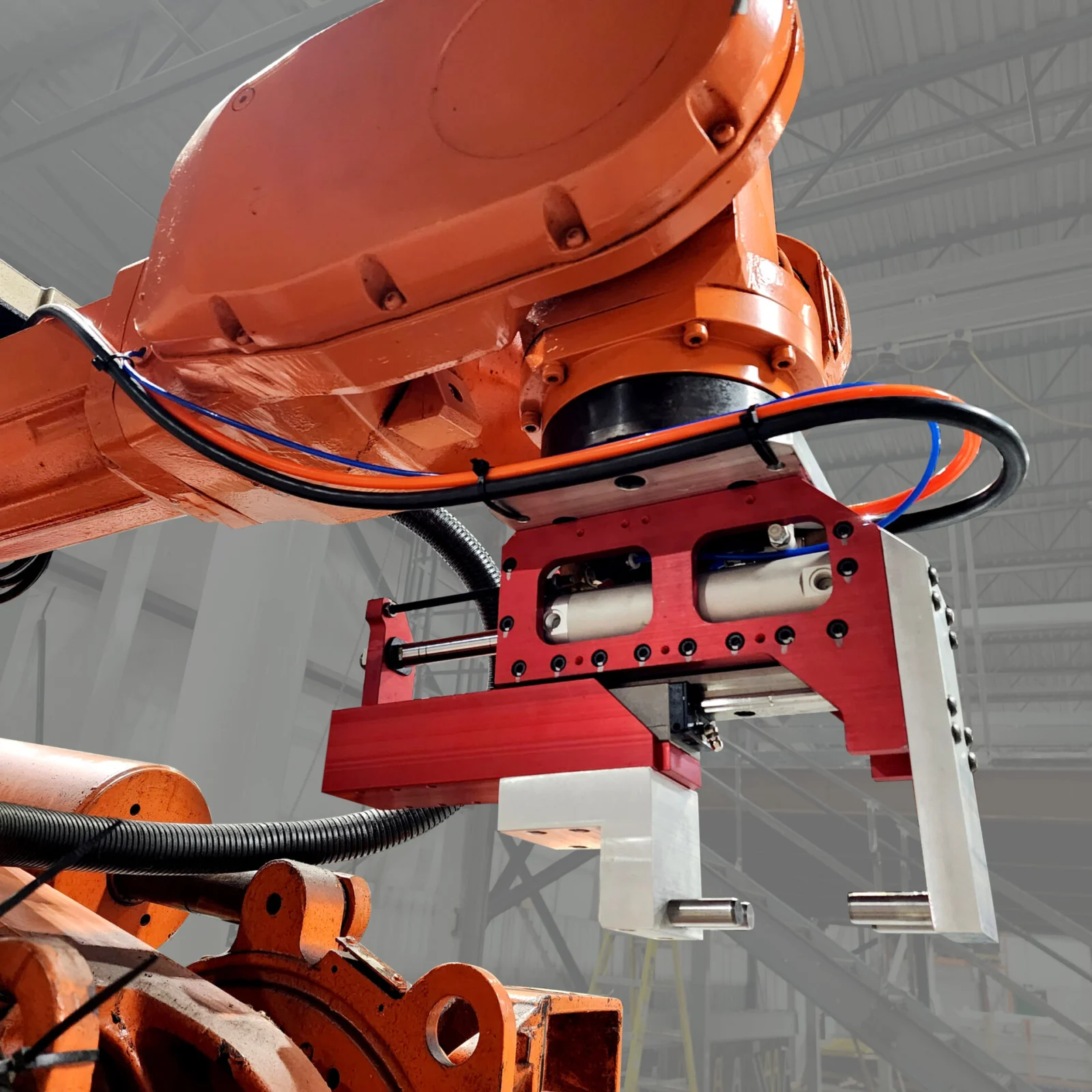
Joint, gripper and end-effector components require suitable access for fasteners, motion and assembly. Review pivot locations and the relationship between mounting features.
Inspection priorities: Joint alignment, bore location, contact surfaces and any weight-sensitive sections.
Read the engineering notes
Supports connect motors, bearings, sensors and structural members. Review machining datums, clamping access, hole patterns and the relation between mounting planes.
Inspection priorities: Hole location, mounting-plane alignment, threads and deburring. Pattern errors can force fasteners or shift the attached motor or sensor.
Read the engineering notes
Locating blocks, pins and support features establish a controlled relationship to the workpiece. Review loading access, clearance and mounting of the fixture itself.
Inspection priorities: Locating geometry, reference faces, contact surfaces and replaceable wear features.
Custom machined parts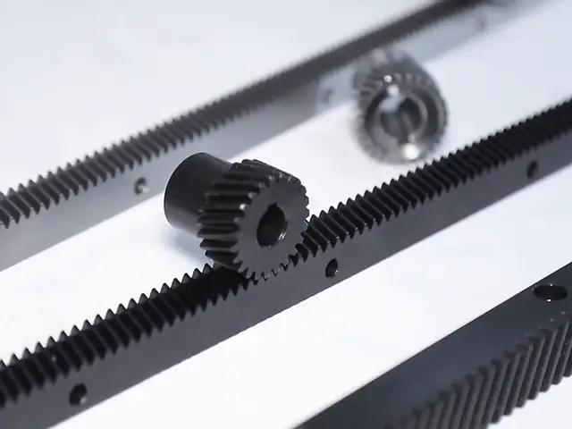
Gears, racks, worms and timing pulleys require a drawing-specific review of tooth geometry and the manufacturing route. Specify module or pitch, pressure angle, tooth count, mating geometry, material and heat treatment.
Agree tooth accuracy, backlash, datum references and the required inspection evidence. Tooth cutting, heat treatment, finishing and gear inspection are planned together with the quotation.
Define thread type, engagement, shoulder length, mating faces and deburring. Review inspection of the features that locate the assembly.
Confirm the current drawing, mounting pattern, cutouts and finish. For a replacement, identify any fit or interface changes before manufacture.
Review the model, cutter access, thin sections and mounting datums. Specify balancing or special testing separately where needed.
PROJECT INQUIRY
Send the current drawing, material, quantity and any inspection or finishing requirements. An engineer replies within one business day.
Request a Quote