5-AXIS CNC MACHINING

Robot Joint Housing: 5-Axis Machining Example

A typical robot joint housing in 7075-T6 aluminum: two coaxial bearing bores, a motor flange and angled cable passages in a thin-walled body. This page shows how such a part is usually reviewed, machined and inspected.

Request a Quote
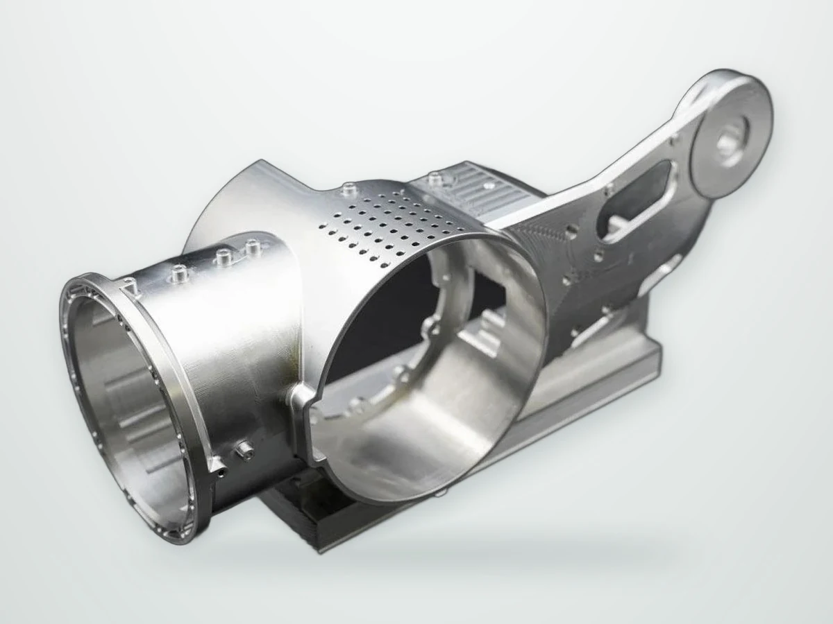
Machined aluminum robot joint housing with coaxial bearing bores and a perforated thin wall shell

Typical requirements

Component
Robot joint or reducer housing
Material
Aluminum 7075-T6 (6061-T6 is a common alternative where strength allows)
Typical process
Indexed 5-axis milling, finish boring
Typical critical features
Bearing bores to H7, coaxiality around 0.01 mm
Typical finish
Hard anodize with bearing bores masked
Typical inspection
First article inspection on CMM, dimensional report

Engineering considerations

  • Bearing bores on opposite sides of the housing usually need to share one axis closely, so a strain-wave or planetary reducer runs without unintended preload.
  • Cable passages and the motor flange often sit at compound angles to the main axis, which a 3-axis setup cannot reach without re-fixturing.
  • Thin walls around pockets can distort as material is removed from a solid billet, so stock allowance and machining sequence matter.
  • Hard anodizing builds up on bearing fits unless the bores are masked or finish-machined after coating.

Typical manufacturing route

01

DFM review

Confirm the datum scheme with the design owner, consider a temporary clamping boss removed in the final operation, and agree masking areas before quotation.

02

Roughing and stress relief

Rough the billet with uniform stock allowance and allow it to rest before finishing to release machining stress.

03

5-axis finishing

Finish the bearing bores, motor flange and angled passages in one clamping where the geometry allows, so their relationship is held by the machine rather than by re-fixturing.

04

Masking and anodize

Plug bores and threads before hard anodizing, then remove the clamping boss and finish that face last. That face stays uncoated, so the drawing has to allow a bare area there; if it must be anodized as well, the boss comes off before coating instead.

Typical inspection plan

  • First article inspection on CMM: bore diameters, coaxiality, flange position and face perpendicularity.
  • Bore diameters checked again after anodizing with bore gauges to confirm the specified fit.
  • Coating thickness checked on anodized faces, with a dimensional report referenced to the drawing revision.

The actual tolerances, inspection scope and records are agreed for each drawing during quotation.

PROJECT INQUIRY

Request a quotation for a similar component

Send the drawing, material, quantity and the features that control assembly. An engineer replies within one business day; NDAs are signed on request.

Request a Quote
WhatsApp