METAL 3D PRINTING

SLM Printed Manifold with Internal Channels

A typical compact hydraulic or air manifold produced by selective laser melting, with curved internal channels that cannot be drilled, then CNC-finished on every sealing face and port.

Request a Quote
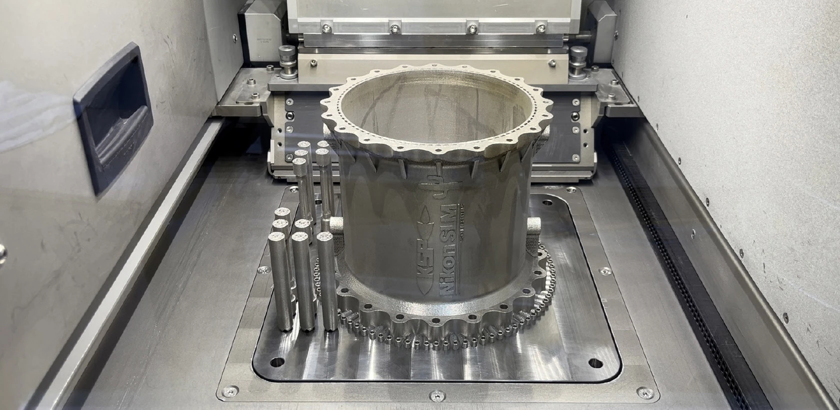
Metal printed component in the build chamber of a laser powder-bed fusion system

Typical requirements

Component
Manifold block with internal channels
Material
AlSi10Mg
Process
SLM, stress relief, CNC finishing
Critical features
Port threads, O-ring grooves, sealing faces
Finish
Bead blast; machined faces Ra 1.6 µm
Inspection
Channel flow check, CMM on machined features

Engineering considerations

  • A drilled-and-plugged design relies on cross drillings that can leave dead zones and need many sealing plugs.
  • Curved channels need to remain self-supporting during printing so no supports are trapped inside.
  • As-printed surfaces are usually too rough for O-ring seals and threaded ports.
  • Machining datums need to be designed into the printed blank so the CNC operation can locate it reliably.

Typical manufacturing route

01

Design for additive

Channels are redesigned as smooth curves with self-supporting cross sections, and machining stock is added on sealing faces and ports.

02

SLM printing

Parts are oriented to minimise supports on functional faces and printed in AlSi10Mg on a powder-bed fusion system.

03

Post-processing

Stress relief before removal from the build plate, support removal and powder clean-out of every channel.

04

CNC finishing

Sealing faces, O-ring grooves and threaded ports are machined from printed datum pads in a dedicated fixture.

Typical inspection plan

  • Every channel checked for blockage and loose powder with compressed air before shipment. Where the manifold carries pressure or has a cleanliness limit, the leak or pressure test (medium, pressure, hold time and allowed leak rate) and the cleanliness requirement are agreed in the quotation.
  • Machined faces, port positions and thread gauging inspected on CMM and with thread plug gauges.
  • Surface roughness of sealing faces verified with a portable roughness tester.

Applying this to your part

The actual route, tolerances, inspection scope and records are agreed for each drawing during quotation.

PROJECT INQUIRY

Request a quotation for a similar component

Send the drawing, material, quantity and the features that control assembly. An engineer replies within one business day; NDAs are signed on request.

Request a Quote
WhatsApp