TRANSMISSION COMPONENTS

Straight Bevel Gear Pairs

Matched straight bevel pairs for 90 degree drives, with hubbed blanks, H7 bores and tooth contact set by mounting distance rather than by the outside diameter.

Request a Quote
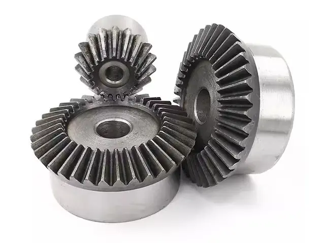
Machined steel straight bevel gear pairs with hubs, keyed bores and back faces

Typical requirements

Gears
Straight bevel pinion and gear, supplied as matched pairs
Shaft angle
90 degrees
Material
42CrMo4 (1.7225) alloy steel
Bores
H7 fits, with keyways or set-screw holes on the hubs
General tolerance
ISO 2768-m
Inspection
Bore fit, mounting distance, tooth runout to the bore, contact check of each pair

Engineering considerations

  • Pitch cone angles follow from the ratio. For a 1:3 pair at 90 degrees they are about 18.4 and 71.6 degrees. Contact depends on mounting distance, so each gear is measured from its own back face and bore rather than from the outside diameter.
  • Pinion and gear are cut, checked and packed as a pair. The contact pattern belongs to the pair, not to each gear on its own.
  • On small pinions the hub keyway or set-screw hole sits close to the tooth root. Holes are drilled after the bore is finished, and the bore is rechecked afterwards.
  • Where pairs are hardened, the drawing states which faces are finished after heat treatment, so bore and back face stay true to the teeth.

Typical manufacturing route

01

Drawing review

Tooth data, cone angles, mounting distance, bore fits and any heat treatment are confirmed for each pair before programs are written.

02

Blank turning

Bore, back face and cone surfaces are turned in one clamping, so the teeth are later cut and checked from the same reference.

03

Tooth cutting

Teeth are cut to the drawing data, with pinion and gear kept together as a matched pair.

04

Secondary features

Keyways and set-screw holes are machined, tooth edges are deburred, and each pair is marked and packed together.

Typical inspection plan

  • Bores checked with plug gauges against the H7 limit.
  • Mounting distance measured from the back face, and tooth runout on a mandrel through the bore.
  • Where the drawing requires it, each pair is rolled together to check the contact pattern.
  • Tooth data, keyway width and general dimensions recorded on the inspection report.

Applying this to your part

The actual route, tolerances, inspection scope and records are agreed for each drawing during quotation.

PROJECT INQUIRY

Request a quotation for a similar component

Send the drawing, material, quantity and the features that control assembly. An engineer replies within one business day; NDAs are signed on request.

Request a Quote
WhatsApp