MOLD MAKING & INJECTION MOLDING

Two-Cavity Unscrewing Mold for a Threaded Cap

A typical production mold for a transparent polycarbonate end cap with an internal thread, released by a rotating core, with DFM changes agreed before steel is cut.

Request a Quote
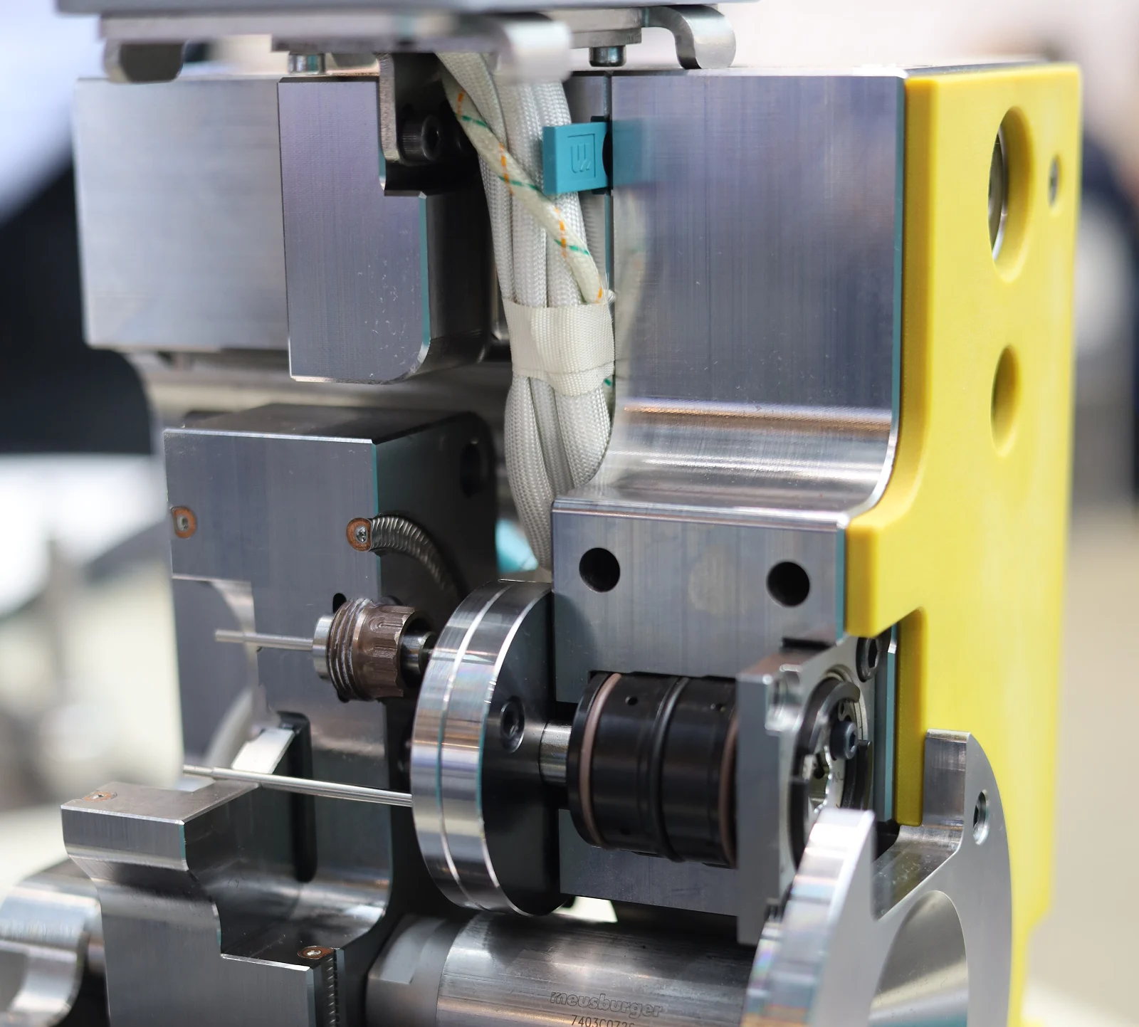
Unscrewing injection mold with rotating thread core and gear drive

Typical requirements

Component
Threaded end cap
Material
Transparent polycarbonate
Mold
2-cavity, 2-plate, cold runner
Steel
H13 inserts, 48 to 52 HRC; S50C mold base
Release
Rotating thread core, stripper plate
Finish
SPI A3 cavity and core polish
Deliverables
Mold DFM report, T1 samples, dimensional report

Engineering considerations

  • An internal thread cannot be stripped off the core without damaging a clear, cosmetic part.
  • Uneven wall thickness around the thread root can produce visible sink marks in a transparent material.
  • The end of the thread may need a modified run-out so the core can disengage cleanly and the cap seats against its mating part.
  • Small cross holes cannot be molded without side actions, which add cost and parting lines on the cosmetic surface.

Typical manufacturing route

01

Mold DFM

A full DFM report covers parting line, gate type and position, draft, wall thickness, cooling and ejection, with before-and-after proposals for each issue.

02

Part changes

Material is cored out to even the wall section and the thread run-out is modified; cross holes can be moved to a post-machining operation.

03

Tool build

H13 cavity and core inserts are machined, hardened and finished by wire EDM and polishing; the rotating core is driven by a gear train.

04

Trial & samples

Sub-gated cavities are filled and balanced at T1, then samples are measured and submitted with the process settings.
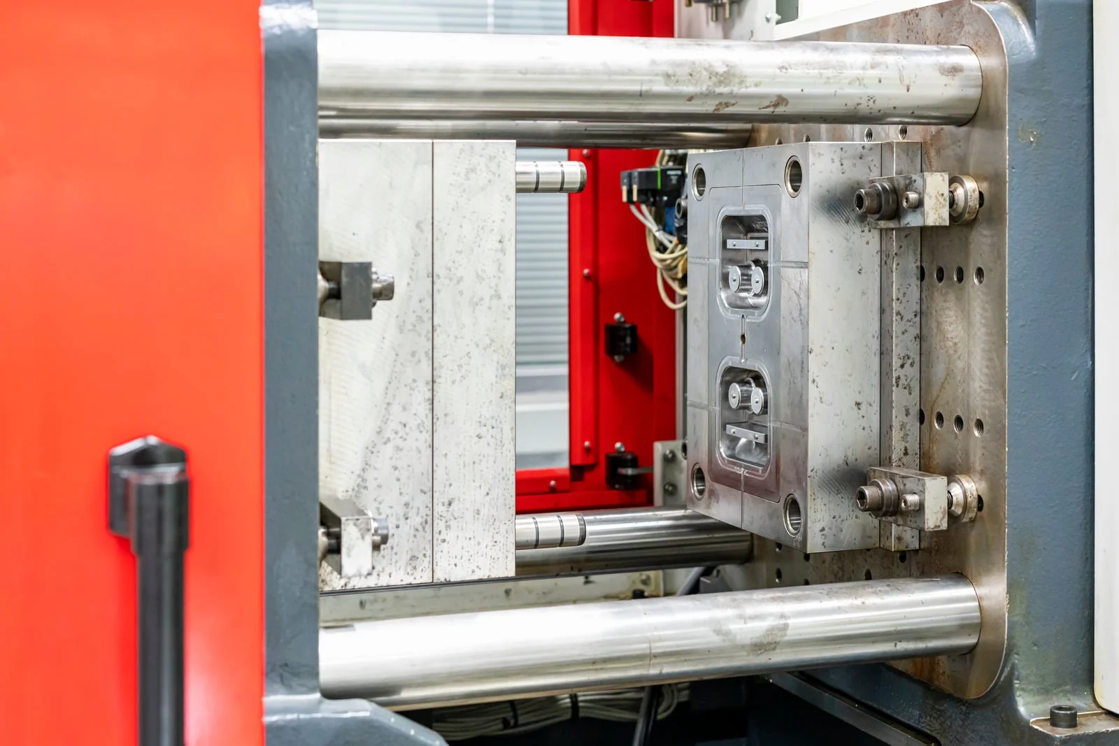
Injection mold mounted between the platens of a molding machine
At T1 the mold runs in the press, and the first shots show whether threads, gates and ejection work as planned.

Typical inspection plan

  • Parting-line and insert mismatch checked during mold assembly against the agreed limit.
  • Thread form checked with go/no-go gauges and assembly trials against the mating part.
  • T1 samples measured on the 2D vision system and CMM, with a dimensional report covering every drawing dimension.
  • Cosmetic inspection of the clear surfaces for sink, flow lines and gate vestige under agreed lighting.

Applying this to your part

The actual route, tolerances, inspection scope and records are agreed for each drawing during quotation.

PROJECT INQUIRY

Request a quotation for a similar component

Send the drawing, material, quantity and the features that control assembly. An engineer replies within one business day; NDAs are signed on request.

Request a Quote
WhatsApp