DFM · TECHNICAL ARTICLE
DFM for CNC Machined Parts: Nine Principles and How to Run a Design Review
By Martin Ji, TOVILON Precision ·
What a design for manufacturability review of a CNC part should check, what it should hand back to the designer, and the nine principles behind those checks.
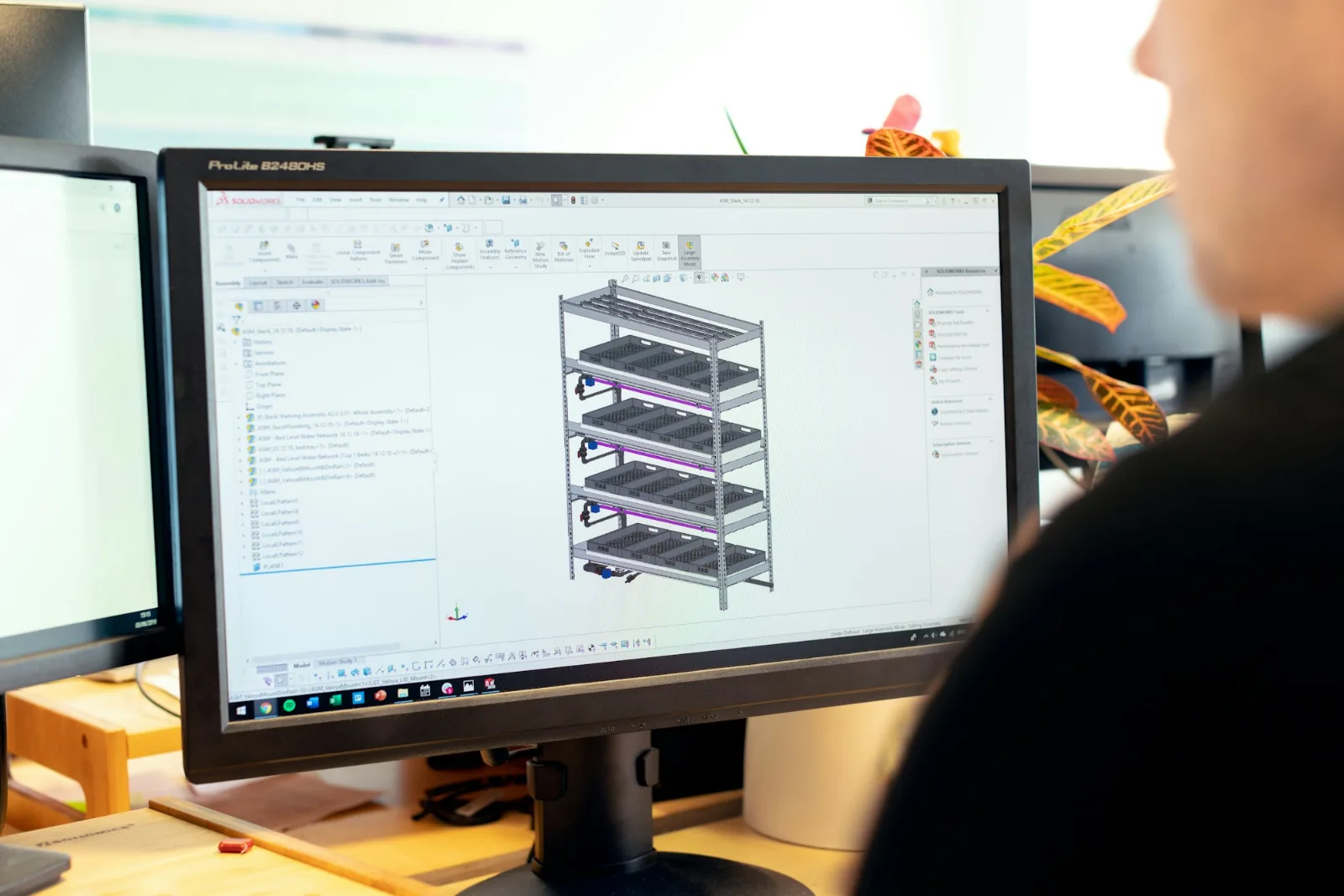
A DFM review of a CNC part is useful when it ends in a short list of decisions. Which internal corners force a small cutter and a slow finishing pass. Which faces need another setup, and whether moving a datum would remove it. Which tolerances add a reaming, grinding or CMM step that the part does not actually need. Each item is marked on the drawing with a proposed change. Anything that touches function stays with the designer to approve.
Resolving the high impact issues early is usually far cheaper than dealing with the same issues later. Moving a hole on the model takes a few minutes. Moving it after the fixture is built means a new fixture and new first parts. That is the practical case for doing DFM before volume production: a manufacturability problem tends to get more expensive with every stage it survives.
What a DFM review should hand back
The table shows the kind of findings that come up on machined aluminum housings and plates, written the way we return them. They are typical examples, not results from a particular customer part.
| What the drawing says | Why it costs time or money | Proposed change | Who decides |
|---|---|---|---|
| R0.5 internal corners in a pocket 25 mm deep | Needs a cutter of about 1 mm diameter reaching 25 mm. It cuts slowly and deflects, so the walls need extra passes. | R3 corners if the mating part allows, or a relief cut in the corner | Designer |
| Bearing bore on one face, mounting holes on the opposite face positioned from it | Two setups. Any error in reclamping goes straight into the hole position tolerance. | Machine both from one clamping on a 5-axis machine, or dimension the holes from a datum on their own face | Datum: designer. Route: us |
| Flatness 0.01 mm on a 200 mm long, 6 mm thick plate | Thin plate moves when it is unclamped. Holding 0.01 mm usually needs stress relieved stock and a separate light finishing pass, sometimes grinding. | Confirm whether 0.02 mm works for the assembly. If not, keep 0.01 mm and price the extra operation openly. | Designer |
| M3 tapped holes 12 mm deep in 6061 | Small taps at 4 × diameter break easily, and a broken tap can scrap a finished part. Engagement beyond about 2 × diameter adds little strength in aluminum. | Thread depth 6 mm with a slightly deeper drill | Designer |
| ±0.02 mm in the title block for every dimension | Every feature becomes a measured feature, including chamfers and clearance holes. | ISO 2768-m as the general tolerance, with tight limits only on fits and datums | Designer |
| Anodized part, bore toleranced as H7 with no finishing note | Nobody can tell whether H7 applies before or after the coating, and the coating takes up most of the band. | State that the bore is measured after anodizing and give the coating thickness, or mask the bore | Designer |
For parts that work together, the review should also run a quick tolerance stack-up across the mating parts, so a tight tolerance on one part is not quietly making up for a loose one on another.
Sort the list by effect on function, manufacturing risk and cost, so the items that change the fit or the price are read first and do not get lost among preferences.
Nine DFM principles at a glance
Process
Pick machining, molding or printing from the geometry and the quantity, not from habit.
Simplicity
Every feature should earn its place. A cosmetic chamfer or pocket still needs a tool, a setup and a check.
Assembly
Let parts locate on pins or shoulders so the assembler does not have to align them by eye.
Standardize
One thread size and one hole size where you can. Each odd size is another tool in the machine.
Materials
Specify alloys and tempers that are easy to buy in the stock form you need, in the quantity you need.
Tolerance
Hold tight tolerances on fits and datums. Everything else can follow a general tolerance standard.
Environment
Temperature, load, coolant or cleaning chemicals in service can rule out an alloy or a finish early.
Review & iterate
Check the drawing again after each change. Fixing one feature often moves a datum or tolerance somewhere else.
Prototype & test
Build a few parts and test them in the assembly before the drawing is released for production.
How production volume changes DFM decisions
The same part can be right for machining at 20 pieces and wrong for it at 20,000. Settle the expected quantity over the life of the part before the review, because it decides which changes are worth making.
| Target volume | Typical route | DFM questions to settle early |
|---|---|---|
| 1 to 50 pcs | CNC machining, 3D printing | Can the part be held and reached in few setups? Are tolerances only tight where function requires? |
| 50 to 5,000 pcs | CNC machining with dedicated fixtures, metal or polymer printing, soft tooling | Can fixtures be shared across variants? Which features justify secondary operations? |
| 5,000 pcs and above | Injection molding, die casting, CNC finishing of critical features | Are draft, uniform wall thickness, gate location and parting line defined before steel is cut? |
Standard features machine faster
A good share of the savings on a machined part comes from small, unglamorous choices. Use one or two thread sizes instead of five. Size internal radii to standard end mills so a pocket can be cut with one tool. Give all operations a common datum scheme, so the part is measured the same way it was held. None of this usually limits the design, but each odd size can add a tool change, a setup or a gauge.
Check the first parts against the review
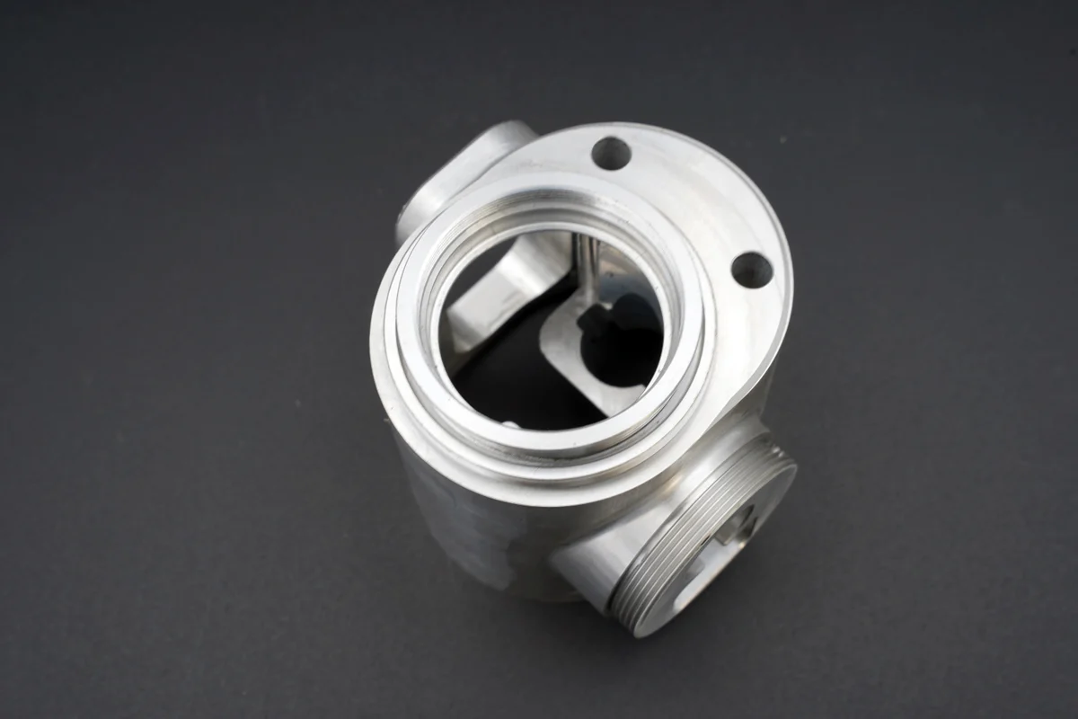
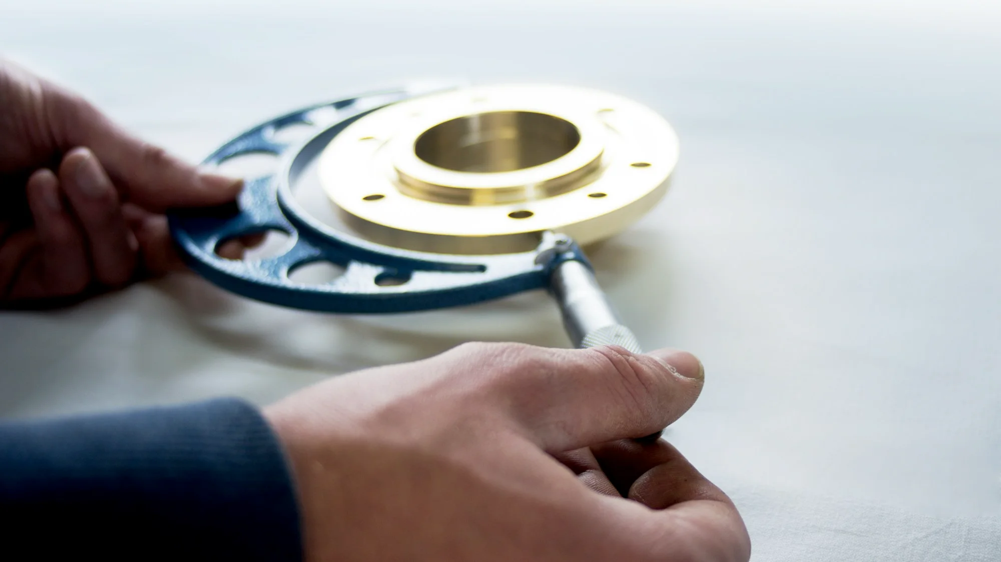
When the first parts come off the machine, measure the features the review flagged, not only the dimensions marked critical. If a relaxed tolerance still holds comfortably, the change was right. If a thin wall or a far hole drifts, something about workholding or stock was missed and the route needs another look before the next batch. Machining simulation catches collisions and gouges before cutting, but it cannot show how a thin wall moves after unclamping. Measured parts do.
Molded and cast parts need a different list
For molded or cast parts the review adds draft angles, uniform wall thickness, the parting line, gate location and ejection, and all of it has to be settled before steel is cut for the tool. See how this works in our mold DFM process and in the two-cavity unscrewing mold example.
When you send the CAD model, include the drawing and the quantity you expect over the next year as well as the first order. That number decides whether a fixture, a second setup or a tolerance change is worth it, and it usually comes from purchasing rather than the designer, so a short cross-functional review with design, purchasing and quality saves a round of emails. We mark up the drawing and send the questions with the quotation. See also our manufacturing capabilities and inspection process.