TECHNICAL GUIDE
Drawing Review, Datums and Fixturing: What Happens Before the First Cut
By Martin Ji, TOVILON Precision ·
The drawing problems that hold up a CNC quotation or send a part back, what each one looks like on the drawing, and how to state it clearly before machining starts.
Many of the questions that come back with a CNC quotation are not about whether the part can be made. They are about what the drawing actually asks for. A bore that is one size in the model and another on the drawing. A position tolerance with no datum. A note that says “anodize” and nothing else. Most take a minute to answer, but the quote waits until someone does. If nobody asks, the machinist has to guess, and a guess is hard to inspect against.
This guide is about the drawing itself, the part of precision machining that happens before the first cut. Design changes that make a part cheaper to machine are covered in our DFM guide, and what changes when an approved prototype goes to repeat orders is covered in releasing a CNC prototype for repeat production.
Drawing issues that stop a quotation
Typical examples, with the question each one raises and a version that answers it. The values are illustrative.
| On the drawing | Question it raises | Clearer version |
|---|---|---|
| Model at revision B, drawing at revision C, with one bore different between them | Which file wins? | Both files at the same revision, plus a note that the drawing governs where they differ |
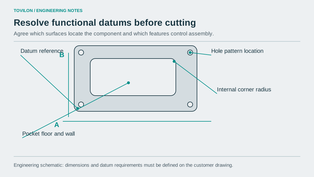
| ⌀0.05 position on a hole pattern, no datum reference | Position relative to what? Different datums mean different setups and different measured results. | Reference the face and bore that locate the part in the assembly, for example ⌀0.05 | A | B |
| “Anodize black” in the notes | Type II or hard anodize? Do the H7 bores and threads apply before or after the coating? Anything masked? | Type II black, 10 to 15 µm. Bores marked * and all threads masked. Other dimensions apply after finishing. |
| “M6” on a blind hole | How deep is the full thread? How deep can the drill go? | M6 × 1 6H, full thread 12 deep, drill 15 deep max |
| A functional distance built up from three chained dimensions | Each step adds its own tolerance, so the distance that matters is not controlled directly. | Dimension that distance once, from the datum |
| “Polish” with no surface or value | Which faces, and to what roughness? | Ra 0.8 on the sealing face, Ra 3.2 elsewhere |
| No edge note on a part assemblers will handle | Leave sharp edges, or chamfer everything? | Break sharp edges 0.2 to 0.5 mm unless noted |
None of these normally needs a design change. They only need the requirement written down once, in the place where both the machinist and the inspector will read it.
Start from the interfaces
When we review a drawing, the first pass ignores the outline and looks for the assembly interfaces, the surfaces that touch a mating part: bearing seats, locating faces, dowel holes, sealing faces. Those are the features the assembly depends on, and they should carry the datums and the tight tolerances.
A robot motor mount is a good example. The bearing bore has to share an axis with the motor pilot, and the flange face has to be square to that axis. If the drawing dimensions the bore from an outside edge instead, the edge becomes a hidden datum. It is easy to machine to, but it says nothing about how the motor will sit. Moving the reference to the flange face costs nothing on paper and removes the doubt.
The datums decide the fixture
The machining and inspection plan has to reproduce the datum relationships on the drawing, and often the datums become the workholding directly. If datum A is the mounting face and datum B is the main bore, the first setup machines both together, and every later operation locates from them. When the drawing puts the datums on features that cannot be reached in the same clamping, there are two options: add a setup and accept some error between setups, or ask whether the datum can move. Either is fine, as long as it is decided before cutting rather than discovered at inspection. Tool access follows the same logic: a feature the cutter cannot reach from the datum setup forces another setup, and often decides whether the part is better suited to CNC milling, CNC turning or both.
Thin walls and deep pockets add a second question: where can the part be clamped without bending it? A pocketed aluminum housing is often roughed with extra material left as support, then finished once the clamping forces are low. A part that measures correctly while it is still clamped can move after release, so the drawing should say in what condition the part is measured.
What comes back from a drawing review
The useful output is a short, numbered list tied to the drawing: the feature, the question, and a suggested wording where we have one. Anything that changes function is a question for the drawing owner, not a decision for the shop. The same numbers carry into the inspection plan, so each critical feature is measured by the method agreed during the review. Once the answers are in, they go onto the next drawing revision, so the batch after this one does not raise the same questions again.
Send the drawing with its model
Send the drawing and the CAD model at the same revision, with the material, quantity and finish. If you already know which features worry you, say so. We will start there. For what a complete quotation package contains, see how to prepare drawings for a CNC quotation.