
The quality of a machining quote depends on the quality of the request. A complete package cuts down the follow up questions, so the quotation usually comes back sooner. Complex parts may still need a round of drawing review before the price and lead time are final. An incomplete one gets a list of questions, or worse, a price based on assumptions that turn out to be wrong when parts arrive. This checklist covers what to send, what to mark on the drawing and which details most often cause delays or extra cost.
Send a 3D model and a 2D drawing
A 3D model defines the geometry. A 2D drawing defines the requirements: tolerances, datums, threads, finish, material and inspection. Both are needed for any part with fits, threads or controlled features.
- STEP (.step or .stp) is the most reliable neutral format for solid models. It transfers clean solids between CAD systems.
- IGES works but often arrives as surfaces rather than solids, which can need repair before programming.
- Parasolid (.x_t) and native SolidWorks files are also fine when available.
- STL is a mesh format meant for 3D printing. It is not suitable for precision machining because curves are approximated by triangles.
- PDF drawings should be exported from CAD rather than scanned, so text and dimensions stay sharp.
Make sure the model and drawing are the same revision. If they disagree, state which one controls.
Purchasing information
Include these details in the request even if they are already on the title block:
- Part number and revision
- Material grade and condition, for example 6061-T6, 7075-T651, 304 stainless or 42CrMo4 quenched and tempered
- Quantity for the first order, plus expected repeat or annual quantities
- Surface finish and color
- Required arrival date and delivery destination
- Inspection documents required with the shipment
Quoting several quantities, for example 5, 50 and 200 pieces, shows how setup cost spreads across larger batches and helps plan the transition from prototype to production.
Tolerances: tight where it matters, general everywhere else
Tolerances are one of the biggest cost drivers on machined parts, alongside material, geometry and quantity. Every tight limit can add a finishing pass, a slower setup or extra inspection time. A good drawing uses a general tolerance standard such as ISO 2768-m for non-critical dimensions and applies tight limits only to features that control fit or function.
Common examples of features that justify tight tolerances:
- Bearing bores and shaft journals, usually with ISO fits such as H7 or k6
- Dowel pin holes and locating features
- Hole patterns that must align with a mating part
- Sealing faces and O-ring grooves
Cosmetic outlines, pocket depths with no mating part and clearance holes rarely need anything tighter than the general tolerance.
Use datums and GD&T consistently
Datums tell the machinist and the inspector how the part locates in its assembly. Without them, a position tolerance can be read several ways. Choose datums from functional features, such as a mounting face and two locating holes, rather than from edges that are only there for convenience. Position, flatness, perpendicularity and runout callouts are often more meaningful and sometimes cheaper than tight plus and minus limits on every coordinate.
Threads, holes and edges
- Thread standard and class, for example M6x1.0-6H or 1/4-20 UNC-2B
- Full thread depth, not just drill depth
- Whether threaded inserts such as helicoils are required
- Chamfers or edge breaks on functional edges, and a general deburr note
- Internal corner radii, since milling cutters cannot produce sharp internal corners
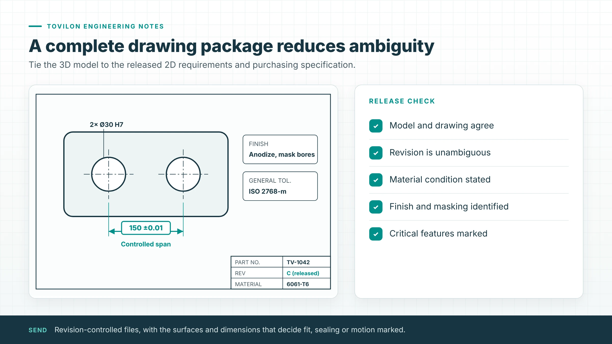
Finish and post-finish dimensions
State the finish type, thickness where relevant, color and the surfaces to be masked. If a bore or thread must meet size after anodizing or plating, say so. Coatings can change close fits enough to cause assembly problems. See our guide to surface finishes for machined aluminum for typical coating thicknesses.
Inspection and documentation
Tell the supplier what evidence you need to accept the parts. Options include a dimensional report on critical features, a full first-article inspection report, material certificates and finish certificates. Numbering the critical dimensions on the drawing (balloons) links the drawing to the inspection report and makes review faster on both sides.
Common gaps that delay quotes
- Model and drawing at different revisions
- Material listed as “aluminum” or “steel” without a grade
- Tight tolerances on every dimension with no indication of which ones matter
- Threads drawn in the model but missing from the drawing
- Finish named but no masking or post-finish dimensions
- No quantity, or only a prototype quantity when repeat orders are expected
Copy this project summary
Paste this into your inquiry and fill it in:
Part number / revision: ___
Material / condition: ___
Prototype quantity and expected repeat quantity: ___
Critical features and datums: ___
Finish and masked surfaces: ___
Inspection documents required: ___
Required arrival date and destination: ___
Open questions or acceptable alternatives: ___
If the design is not final
You do not need a perfect drawing to start a conversation. If the material, process or tolerance is still undecided, describe what the part does, its operating environment and which requirements cannot change. Ask for alternatives. An engineering review can point out features that are expensive to machine before the design is frozen, which is the cheapest time to change them.
Confidential drawings
If your drawings are confidential, request an NDA before sending files. Our RFQ form accepts STEP, IGES, X_T, SolidWorks, DXF, DWG and PDF files, STL, 3MF and OBJ for 3D printing, and ZIP, RAR or 7Z archives, up to 30 MB each, with no limit on the number of files.