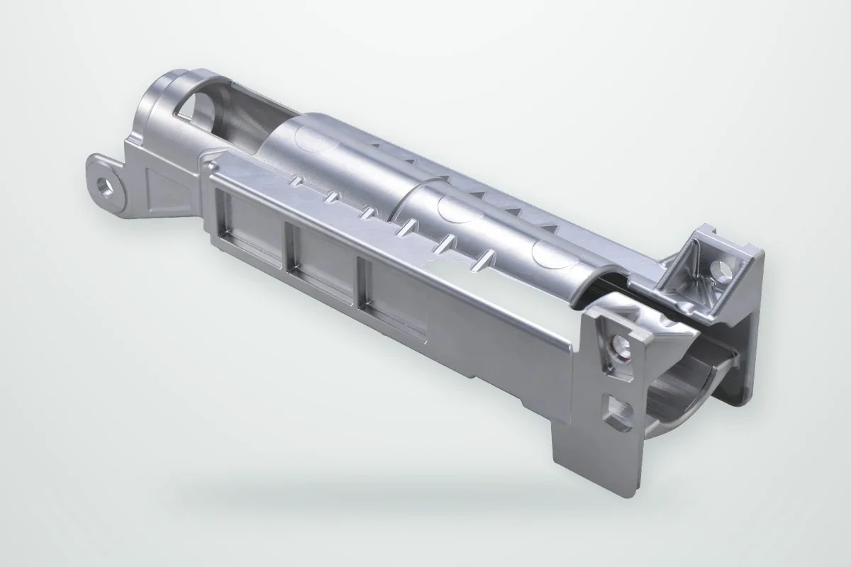
A robot joint housing, a sensor mount or a gearbox cover can look simple on screen. Look closer and you find twenty holes on three faces, chamfers that guide assembly, small internal fillets, a thin wall next to a deep pocket and two bores that must stay coaxial. None of these features is difficult on its own. Put together, they decide how many setups the part needs, which tools can reach each surface and whether the part comes off the machine in tolerance.
Feature-based machining is a practical way to deal with that complexity. Instead of treating the model as one solid block to be cut away, engineers break it down into machinable features, plan how each one will be produced and check the route in simulation before any metal is cut. This article explains how that works, where it prevents problems, and what a buyer can send to get a better quotation on a complex CNC part.
From CAD model to machining plan
A 3D model describes the finished shape. It does not say which face to machine first, how to hold the part, or which features need their own operation. Two manufacturers can receive the same STEP file and plan completely different routes, with different cycle times, risks and prices.
Feature recognition closes that gap. By identifying holes, pockets, slots, chamfers, fillets and datum faces, the engineer can link each piece of geometry to a machining operation, a tool and an inspection step. It also shows early which features are routine and which ones will drive cost or risk.
Common features and what they mean for machining
| Feature | Typical machining concern | What helps on the drawing |
|---|---|---|
| Holes and bores | Depth, position, coaxiality, holes on angled faces, intersecting holes | Position tolerance to functional datums, fit class on bearing bores, full thread depth |
| Chamfers | Consistency across mating parts, burrs at hole entries | Chamfer size where it matters for assembly, a general edge break note elsewhere |
| Internal fillets | Small radii force small cutters, longer cycle time, tool deflection | Largest radius the design allows, ideally slightly larger than a standard cutter radius |
| Deep pockets | Long tools, chatter, chip evacuation | Realistic depth to width ratio, floor radius, wall finish only where needed |
| Thin walls | Deflection during cutting, distortion after release from the fixture | Minimum wall thickness, flatness requirement, whether stress relief is acceptable |
Recognizing these features at the quotation stage makes it possible to say early that a part needs a dedicated finishing pass, special tooling or extra inspection, instead of discovering it after the first batch.
Planning the machining sequence
Once the features are known, the next step is the process plan: in what order material is removed, on which machine, with which tools and how the part is held in each setup. The sequence matters because every operation changes what is left for the next one.
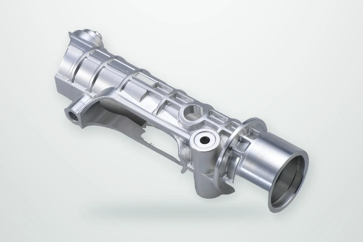
Take a precision aluminum housing that needs facing, pocket milling, drilling, chamfering and finishing. If the main datum face is machined late, earlier features have nothing reliable to reference. If a thin wall is finished before the surrounding material is removed, cutting forces can push it out of position. If the clamping points sit on a surface that will later be machined, the part can lose its location halfway through the route.
A robust process plan for a complex part usually covers six points:
- Datum strategy: which faces and holes locate the part in every setup and during inspection.
- Operation order: roughing, semi-finishing and finishing, arranged so that critical features are cut from a stable reference.
- Tool access: whether each cutter and holder can reach its surface without interference.
- Workholding: clamping positions, fixture clearance and how well the part is supported during heavy cuts.
- Tolerance relationships: which dimensions depend on each other and how setup changes could stack up.
- Inspection points: what is measured in process, what is checked at first article and what goes on the final report.
For multi-step routes, programmers often work with in-process stock models that show the part after each operation. Planning the next step from the material that is actually left, rather than from the original block, avoids air cutting and overloaded tools.
Toolpath planning for intersecting features
The toolpath turns the plan into machine movement. On parts with many intersecting features, a good toolpath has to account for more than the finished shape: tool diameter and length, holder clearance, approach and retract moves, and the shape of the remaining stock all matter.
A large cutter clears open areas quickly but cannot follow a tight corner. A small cutter reaches narrow slots and small fillets, but it removes material slowly and deflects more, which affects accuracy and surface finish. The usual answer is a staged approach: a large tool for bulk removal, then progressively smaller tools only where the geometry demands them.
Additional axes change the picture again. Indexed 3+2 and simultaneous 5-axis machining can reach angled holes and faces that would otherwise need extra setups, which helps keep related features on one datum. They also bring more complex tool orientations and machine motion, which is exactly where simulation earns its place. The shortest path is not always the best one. A route that causes sudden direction changes, unstable tool engagement or frequent tool changes can be slower and less accurate in practice.
Machining simulation and collision checks
Even a carefully planned toolpath can hide problems that are hard to see in the code. The tool, holder, workpiece, fixture and machine head all move through the same space, and a path that looks correct at the cutting edge can still bring the holder into a clamp.
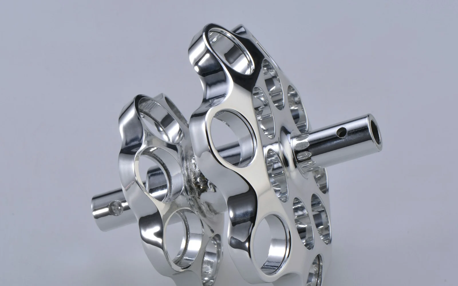
Machining simulation runs the program in a virtual environment first. Depending on the software and how completely the machine is modeled, it shows material removal step by step and checks for interference between the tool, holder, part, fixture and machine components. It is most useful for catching four kinds of error:
- Overcut: material removed beyond the intended surface, often scrapping a part when it hits a mating face.
- Leftover material: regions the route never reaches, leading to out-of-tolerance features or manual rework.
- Tool and fixture collisions: damage to tools, fixtures and parts, and in severe cases to the spindle.
- Machine interference: on multi-axis moves, the head or rotary table approaching the fixture even though the cutting path itself is valid.
Simulation is a planning tool, not a replacement for setup verification or measurement. Its results are only as good as the machine model, tool and fixture definitions and stock geometry behind it. Used properly, it lets the programmer adjust orientations, change the order of operations and fix errors before the first part is cut, which matters most on expensive material or a one-off prototype.
Stock, roughing and finishing allowance
Many complex parts start as solid blocks and end up as mostly pockets, cavities and thin sections. When the stock model does not match the starting material, the program wastes time cutting air or overloads a tool where more material remains than expected.
Roughing removes material efficiently while keeping the part stable. Finishing sets the final size, surface and geometry. Between the two, enough allowance has to remain for the finishing tool to cut cleanly and correct any movement from roughing. The right amount depends on the material, the geometry, the workholding and the tolerance.
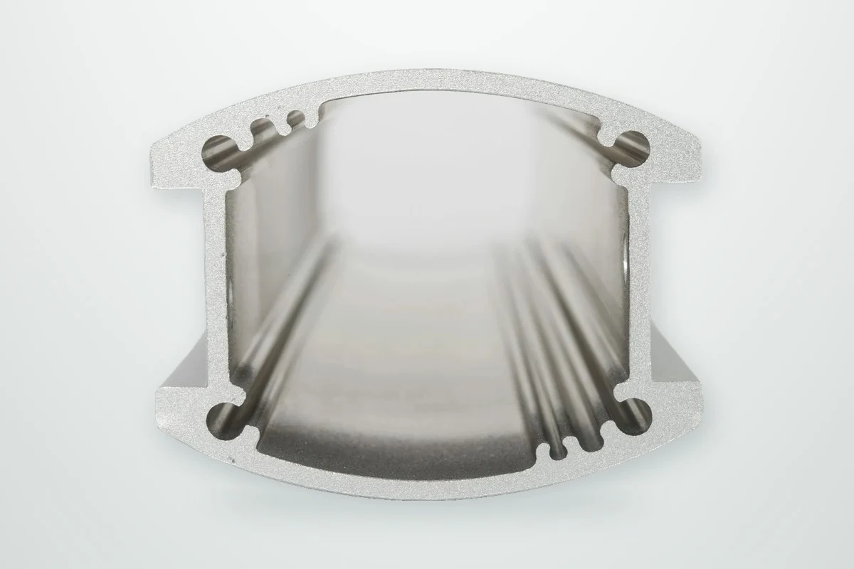
Thin-wall aluminum housings and asymmetric parts need extra care. Removing large volumes from one side can release internal stress and bend the part. Spreading material removal across both sides in stages, leaving finishing stock until the part has relaxed, and finishing critical faces last are common ways to control distortion. This is why machining efficiency should be judged on the whole route, not on cutting speed alone.
Before programming: review, quotation and repeat orders
Most of the feature problems above are cheapest to fix on the drawing. A short DFM review before quotation picks out internal radii that force long, slow cutters, deep narrow pockets, closely spaced holes and tight tolerances on features that do not control fit, and separates them from the features that really drive machining and inspection.
The process plan pays off a second time on repeat orders. When the datums, operations, tools and inspection points are written down, the next batch follows the same route. Inspection should follow function: hole position, flatness, perpendicularity, coaxiality, threads and surface finish on the features that matter for assembly. When a part fails, machine accuracy is only one possible cause; workholding, tool wear, heat, material variation and the order of operations are the others to check. How an approved prototype is released for repeat production is covered in a separate guide.
For the quotation itself, a STEP model and PDF drawing at the same revision, the material grade and condition, the quantities and the features you already know are difficult are the core. The full checklist is in how to prepare drawings for a CNC quotation.
Related reading: 5-axis CNC machining, CNC milling and drawing review before the first cut.
Frequently asked questions
Does every CNC part need machining simulation?
No. Simple prismatic parts on a 3-axis machine rarely need full machine simulation. It becomes valuable on multi-axis work, tight fixtures, deep features close to clamps and parts made from expensive material, where one collision costs more than the time spent checking.
Can feature-based planning reduce the cost of a complex part?
Often, yes. Grouping features by datum and tool reduces setups and tool changes, and a DFM review can remove features that add machining time without adding function. The biggest savings usually come from changes agreed before programming starts.
Why does a thin-wall part move after machining?
Machining releases internal stress in the material and cutting forces push thin sections away from the tool. Balanced material removal, staged roughing, proper finishing allowance and well-placed support during finishing all help keep the final geometry in tolerance.