ASSEMBLY & MECHANISMS

Telescoping Tripod Stand Assembly

A pocket-size tripod stand that folds into a 140 × 35 mm envelope and extends to 610 mm: a stainless body, three folding legs, steel telescoping stages and a finger-pad release, built from machined and purchased parts.

Request a Quote
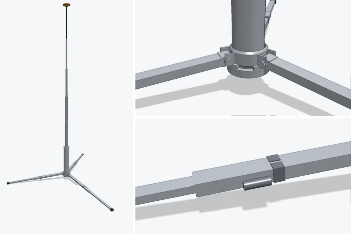
Telescoping tripod stand rendered from its CAD model, with close-ups of the leg hub and a telescoping leg joint

Typical requirements

Components
41 machined and purchased items with final assembly
Material
304L and 304 stainless body, hub and collar; steel telescoping stages
Process
CNC turning and milling, welding, finishing in one setup
Envelope
Fits a 140 × 35 mm gauge stowed; 610 ± 10 mm deployed
Weight target
323 to 357 g without the carry sleeve
Validation
Lock holding, release force and weld joint tests on samples

Engineering considerations

  • After the hub is welded, the three pin holes, the collar bearing face and the weld contour are finished in one setup so the leg axes stay related to each other.
  • The weld bead has to stay inside the modelled envelope, because the folded legs sit very close to the body.
  • A fine spring, a slide and a purchased detent plunger form the release, so fits and spring data are proven on samples before the full build.
  • The release is operated with a finger pad, without tools or a fingernail, and the leg has to lock again on its own.

Typical manufacturing route

01

Fit and stack review

The folding envelope, stop dimensions and leg-to-leg differences are reviewed as one tolerance chain.

02

Parts and purchasing

Machined parts are made while purchased items such as the plunger, spring and seals are sourced and checked.

03

Weld and finish

The hub is welded to the body, then pin holes, bearing face and weld contour are finished in a single setup.

04

Assembly and samples

Sample sets are assembled and tested for locking, release and height before the batch is released.

Typical inspection plan

  • Stowed product checked in the 140 × 35 mm cylinder gauge after finishing.
  • Deployed height measured on a hard floor and leg lengths compared with each other.
  • Lock holding under load and finger-pad release force recorded on sample sets.

Applying this to your part

The actual route, tolerances, inspection scope and records are agreed for each drawing during quotation.

PROJECT INQUIRY

Request a quotation for a similar component

Send the drawing, material, quantity and the features that control assembly. An engineer replies within one business day; NDAs are signed on request.

Request a Quote
WhatsApp