5-AXIS CNC MACHINING
5-Axis CNC Machining for Robot Housings and Complex Parts
Multi-face housings, angled interfaces and contoured components for robotics, automation and industrial equipment. We plan tool access, workholding and CMM inspection around the complete part, from one prototype to repeat batches.
Request a Quote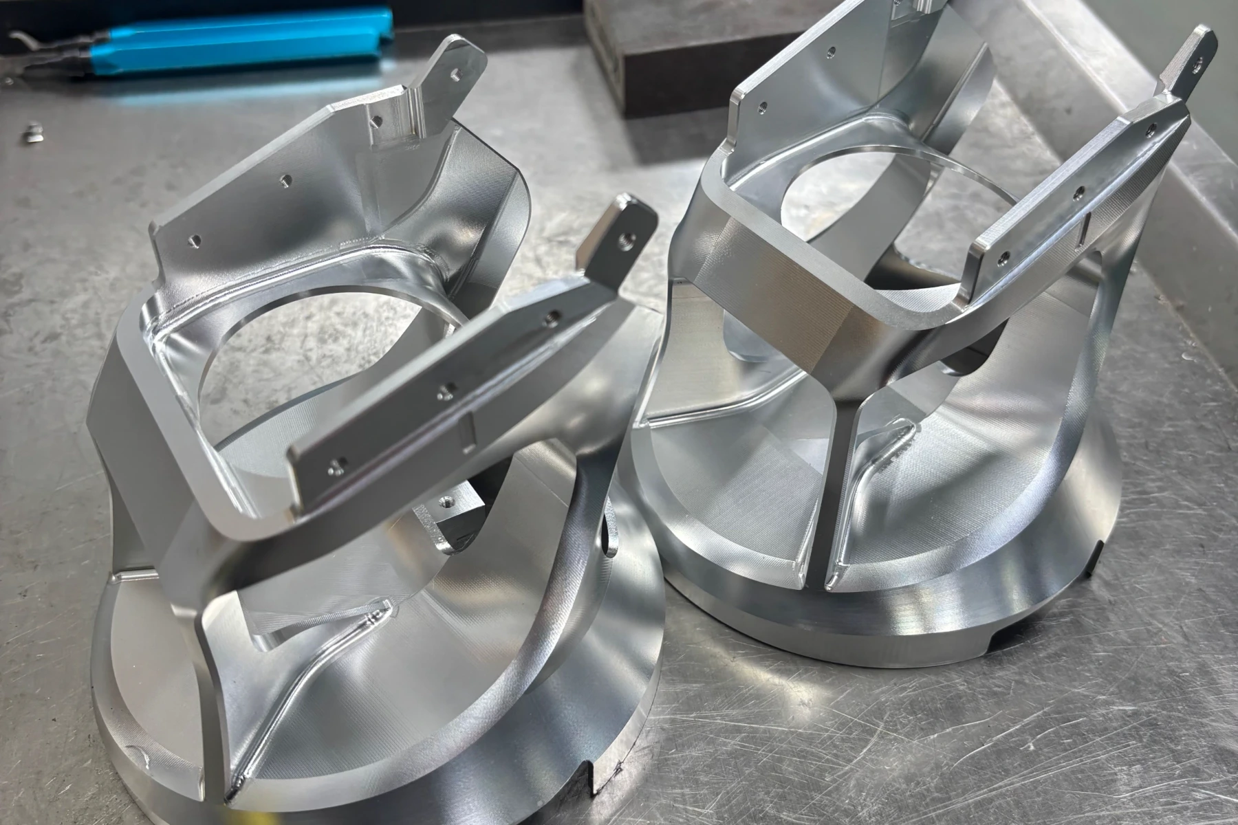
Where five-axis machining adds value
Five-axis machining is most useful when the relationship between features matters as much as each individual dimension. Bringing the tool to several orientations can reduce repeated re-clamping and provide access that is awkward with a fixed spindle direction. The benefit depends on the geometry, not simply the number of machine axes.
Robot joint and link housings
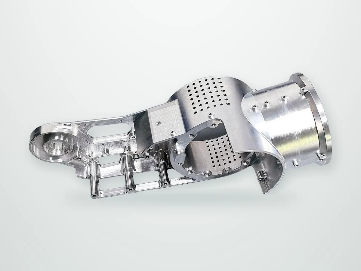
Bearing bores, motor interfaces and mounting faces have to line up. Cutting them in one clamping, from the same datums, is usually the reason to put a joint housing on a five-axis machine.
Angled mounting interfaces
Oblique bores, compound faces and intersecting hole patterns. On a 3-axis machine each angle tends to mean another fixture, and position error builds up with every transfer. Tilting the part keeps them on one reference.
Contoured mechanical parts
Curved transitions and sculpted surfaces where the tool has to follow the surface. These are usually cut with simultaneous motion, although gentle surfaces can sometimes be finished with a fixed tool axis. Either way they need a clean surface model; a mesh or a loosely defined surface is a common source of questions.
Indexed 3+2 or simultaneous five-axis?
Indexed 3+2 machining
The rotary axes orient the part or tool, then remain fixed during the cutting move. This can suit angled holes, multiple planar faces and pockets approached from different directions. It is a practical route when each feature can be cut from a stable orientation.
Simultaneous five-axis machining
Tool orientation changes during cutting. This can help with continuous contours and changing surface normals, but requires suitable machine kinematics, programming and collision clearance. It is not automatically needed for every multi-sided component.
In practice many housings and brackets are made 3+2, with simultaneous motion kept for the contoured faces. Machine travel, rotary limits and the fixture envelope set the size limit.
Solve access and workholding before cutting
Tool reach and clearance
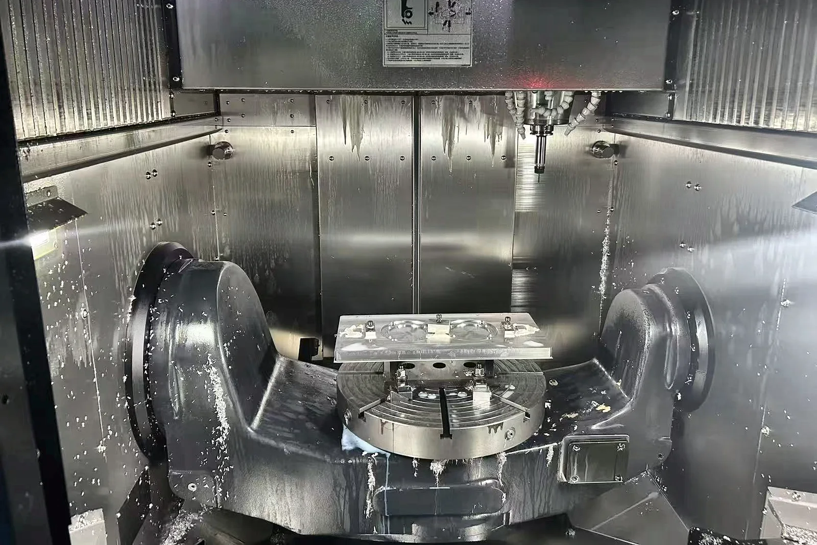
Check the complete tool and holder, not only the cutter tip. Tilting can improve access or allow a shorter tool, but deep cavities, enclosed passages and fixture interference can still limit what is machinable.
Clamping and datum transfer
Leave room for the fixture while exposing the required surfaces. Thin walls and long unsupported sections need a sequence that controls movement as stock is removed. A second setup may still be needed to finish the clamping area.
Surface and edge requirements
Specify functional surfaces separately from cosmetic faces. Identify allowable tool marks, internal radii, edge breaks and burr-sensitive intersections so finishing does not compromise a mating feature.
Material and finish are part of the machining plan
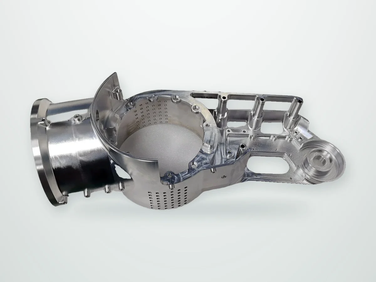
Aluminum housings, stainless steel interfaces and other specified alloys place different demands on cutting stability, chip removal and support. A grade and temper on the drawing, rather than just “aluminum”, lets us plan the cut. For development parts, say if an alternative alloy would be acceptable; it can shorten the lead time when stock is short.
Coatings change bore fits, threads and locating faces, so masking or a size allowance has to be decided before machining. See the material and finish options, and the anodizing allowance guide for the numbers.
Measure the relationships that control assembly
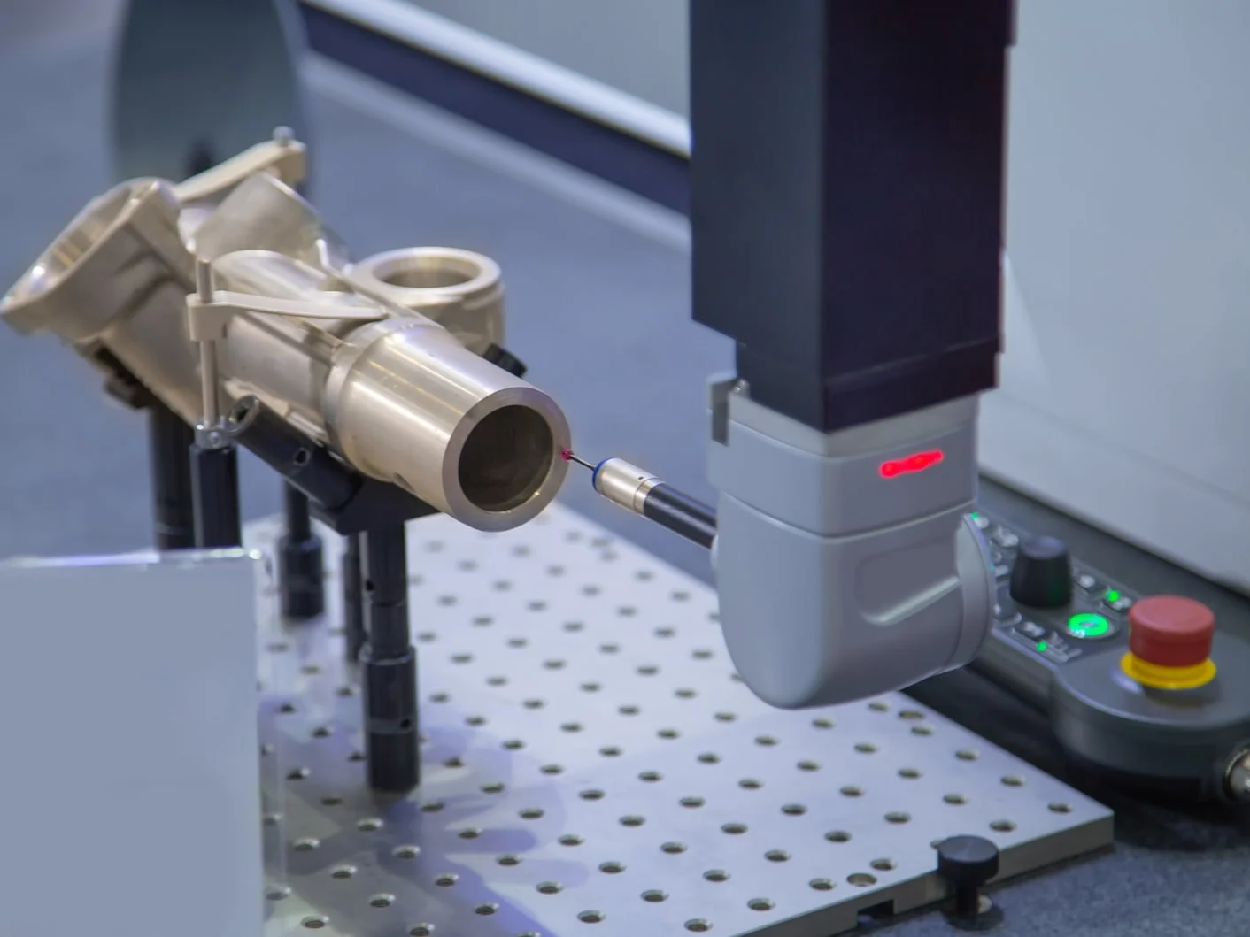
A five-axis route does not replace an inspection plan. Bore positions and face angles are checked from the same datums the part was machined from, and it is worth checking early that a probe can actually reach the angled features.
For a first build, tell us which dimensions decide assembly approval and whether you need a dimensional report. CMM or other methods are chosen to suit the geometry, and the report lists the drawing revision, the features measured, the results and any approved deviation.
Inspection planning and dimensional report exampleFive-axis engineering examples
ROBOTICS
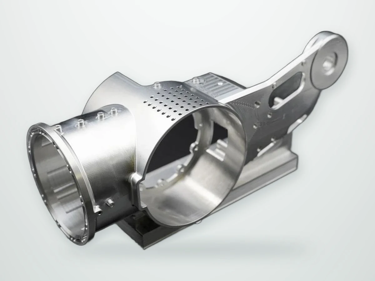
Robot joint housing in 7075-T6
Coaxial bearing bores, angled cable passages and thin walls: how this type of housing is typically machined and inspected.
View the example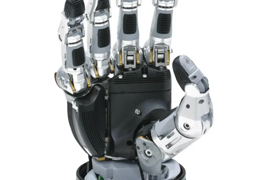
HUMANOID ROBOTICS
Robot hand structural components
Finger links, joint supports and mounting interfaces; review pivot fits and assembly clearance.
View the examplePrepare a useful five-axis RFQ
- Supply a 3D model and dimensioned drawing with the current revision.
- Specify material grade, quantity, production stage and required surface treatment.
- Identify mating bores, datum faces, sealing surfaces and dimensions that determine assembly.
- Note cosmetic requirements, edge conditions, inspection records and requested delivery date.
Our quotation states the machining route, finishing, inspection scope and lead time, and lists any open design questions. Changes to material, geometry or finishing are approved by you before manufacture. NDAs are signed on request before you send restricted drawings.
For a deeper design discussion, read the five-axis robotics machining guide. For simpler prismatic features or rotational parts, compare CNC milling and CNC turning.
Related engineering guides
Five-axis machining FAQ
When is 5-axis machining worth the cost?
When features on several faces must align with each other: bearing bores, angled interfaces or sculpted surfaces. Completing them in one clamping removes re-fixturing error and often reduces total cost compared with several 3-axis setups.
What tolerances do you hold on 5-axis parts?
Critical bores and faces are typically held to ±0.01 mm with positional and coaxiality requirements verified on CMM. Tighter requirements are reviewed feature by feature during quotation.
Do you machine single prototypes on 5-axis?
Yes. The minimum order is one piece, and the program and fixture from the prototype are reused for later batches.