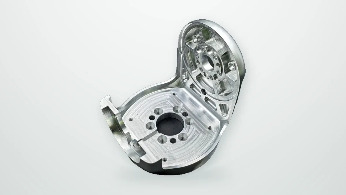
Robot joints combine motion, load transfer and compact packaging. Their metal components must be light enough to limit moving mass, stiff enough to support the assembly and dimensionally controlled enough to locate bearings, motors and reducers. A housing that looks correct externally can still create assembly problems if its bores, mounting faces and hole patterns do not work together.
This makes 5-axis CNC machining for robotic parts an engineering decision rather than a marketing label. Additional tool orientations can help manufacture complex geometry, but the drawing, material, fixtures and inspection plan determine whether the finished component meets its purpose. The same principles apply to collaborative arms, humanoid robots and conventional automation equipment: advanced motion control does not remove the need for reliable mechanical interfaces.
Why robot joint components need precision CNC machining
A joint housing may locate a motor, support a bearing pair and connect a reducer to an arm link. Each interface contributes to the assembly tolerance stack. Bearing-seat size affects fit; bore form and surface texture affect contact; mounting-face orientation influences how components align after tightening.
Positional accuracy matters when a bolt circle must align with a motor flange or gearbox. The relationship between shaft and bearing axes may require control of coaxial alignment, runout or position, depending on the drawing standard and function. Perpendicularity between a locating face and an axis can be more important than the appearance of a nonfunctional external surface.
Precision CNC machining connects these requirements to a repeatable sequence. It cannot compensate for an incomplete specification. Engineers should identify the load path, assembly references and acceptance criteria before selecting a machining process or tightening dimensional limits.
Where 5-axis CNC machining helps on robot parts
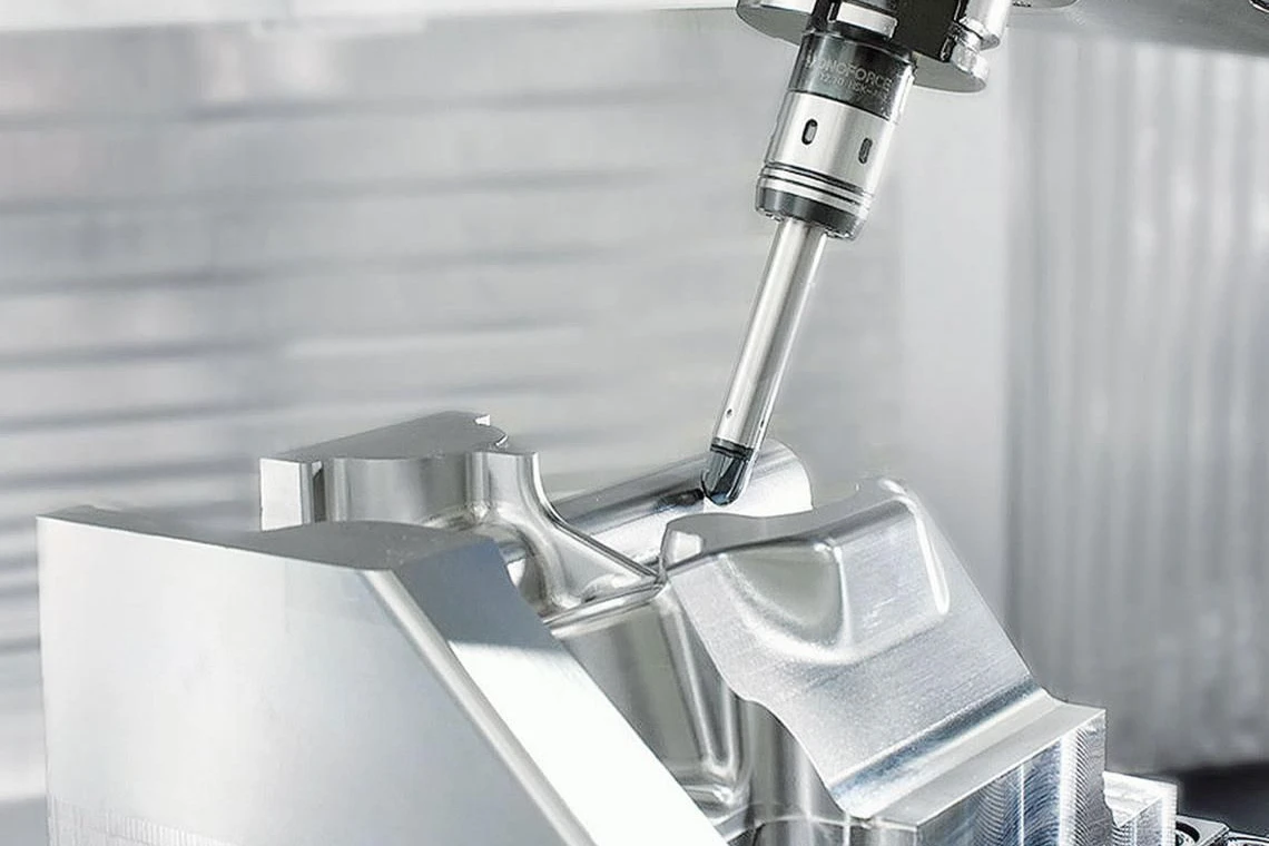
Five-axis machining adds two rotary motions to the three linear axes. In indexed, or 3+2, machining, the part or tool is oriented before a cutting operation. Simultaneous five-axis machining coordinates orientation during the cut. These approaches solve different access and surface-generation problems; they should not be treated as interchangeable requirements.
Multi-face housings can benefit from fewer manual repositioning steps. Angled holes, curved surfaces and mounting features on different faces may become accessible from a common setup. Tilting the tool can sometimes permit a shorter cutter, reducing the deflection risk associated with a long tool reaching into a deep pocket.
Benefits depend on collision clearance, fixture access and the machine’s usable work envelope. Some underside features still require another operation. Five-axis machining does not automatically guarantee micron-level accuracy. Achievable tolerance depends on geometry, material, machine condition, fixturing, thermal stability, tooling, machining strategy and inspection requirements.
Programming must consider the complete setup, including the holder, fixture, stock and machine movements. A toolpath that reaches a surface in the CAD model may still encounter a physical obstruction. Simulation, suitable clearance and controlled prove-out help establish whether an orientation is practical. For procurement, the useful question is which features benefit from the proposed setup and how they will be verified.
Aluminum alloys for robotic components
Aluminum is frequently considered for moving structures because it combines low density with useful machinability. Alloy, temper and stock form must be specified together. A higher-strength alloy is not automatically much stiffer: section geometry and load paths remain central to deflection control.
| Alloy | Typical characteristics | Potential applications |
|---|---|---|
| 6061-T6 | Balanced strength, machinability and corrosion resistance. Approximate density: 2.70 g/cm³. | Joint housings, motor mounts, covers and general structural brackets. |
| 6082-T6 | A structural 6000-series option with good machinability in the T6 condition. Approximate density: 2.70 g/cm³. | Arm links, load-bearing supports and machined frame components. |
| 7075-T6 | Higher strength than common 6000-series choices, with corrosion and finishing considerations. Approximate density: 2.80 g/cm³. | Highly loaded links, compact carriers and strength-limited interfaces. |
These are selection guides, not guaranteed design properties. Confirm the applicable material specification, product form, certification and environment. For 7075, density is approximately 2,800 kg/m³. Material availability and any alternative temper should be reviewed before quotation.
Machining strategy for robot joint housings
Review the CAD and drawing together. Resolve revisions, units, missing tolerances and finishing notes. A DFM review should identify small internal radii, inaccessible intersections, deep pockets and features that create unnecessary setups. Changes affecting function require the customer’s agreement.
Establish datums and workholding. Choose locating faces and axes that reflect assembly intent. Plan how references transfer between operations. Clamping should support the component without squeezing thin walls into a shape that changes after release.
Separate roughing from controlled finishing. Heavy material removal can redistribute residual stress. A staged sequence, balanced stock removal and appropriate finishing allowance can help manage movement in asymmetric housings. Semi-finishing provides an opportunity to check the developing geometry before finishing critical bores and faces.
Control cutting conditions. Long overhangs increase tool-deflection and vibration risks. Thin sections may need local support or lighter cuts. Heat, built-up material and recut chips can damage surfaces or disturb dimensions, so tool selection, coolant delivery and chip evacuation must match the material and pocket geometry.
Complete the finishing route. Deburr edges and internal intersections, clean the part, apply the specified treatment and inspect it in the agreed final condition. A stable result must satisfy the drawing after unclamping and finishing, not only while supported on the machine.
Critical interfaces that decide assembly
Assign tolerances according to function. Unnecessarily tightening every dimension increases machining and inspection effort without necessarily improving robot performance. Discuss the following interfaces explicitly:
- Bearing bores: Define the fit, bore form, surface texture and shoulder requirements needed to locate and support the bearing.
- Shaft bores: Identify the locating axis, engagement length and any runout or alignment relationship to other features.
- Motor mounting interfaces: Coordinate the pilot diameter, bolt pattern and face orientation with the selected motor.
- Reducer and gearbox interfaces: Review centering features, fastener clearance, mating faces and the manufacturer’s installation requirements.
- Bolt-hole patterns: Specify their location relative to functional datums, distinguishing clearance holes from locating features.
- Mounting surfaces: Address flatness, perpendicularity and contact conditions where they influence alignment or clamping.
- Functional datums: Use an unambiguous reference scheme for machining, inspection and assembly.
Consider interacting components rather than approving each part in isolation. Where assembly is constrained, agree the measurement condition. Masked areas, coating allowances and inaccessible measurement locations should be resolved before production.
For example, a housing with two bearing seats should be reviewed around their shared functional axis and the axial location of the shoulders. Checking only the individual bore diameters would leave part of the assembly requirement unresolved. Similarly, a reducer mounting pattern needs a defined relationship to the centering pilot, not merely a collection of hole sizes. This functional approach helps engineers direct effort toward the interfaces that matter.
Combining milling, turning and other processes
Not every robotic component needs five-axis machining. Three-axis milling may be efficient for plates, brackets and accessible pockets. Four-axis indexing can suit features distributed around a component. Five-axis positioning or simultaneous machining becomes relevant when orientation, access or surface geometry justifies it.
CNC turning often suits shafts, sleeves, flanges and rotational bearing carriers. A turned blank may then require milling for flats, slots or mounting holes. Wire EDM can complement milling for suitable through-profiles in electrically conductive material; grinding may address selected planar features.
At TOVILON, the manufacturing route is selected according to geometry, material, quantities and drawing requirements. Where a component calls for four- or five-axis work, the appropriate route and feasibility can be evaluated during engineering review. The axis count alone should not determine the quotation.
See the complex-component machining overview and supporting manufacturing processes for how machining, secondary operations and inspection fit together.
Surface finishing and its effect on fits
An as-machined finish preserves visible tool paths where the specified surface is acceptable. Deburring removes unwanted edge material; controlled edge breaks should remain consistent with the drawing. Bead blasting creates a more uniform matte appearance but can alter edges or critical surfaces if they are not protected.
Polishing changes surface texture and can round edges or affect local geometry. It should be specified for the relevant surfaces rather than assumed to improve every component. Anodizing can provide corrosion protection and color; hard anodizing is often considered for wear resistance.
Anodic coatings involve both penetration into the substrate and outward growth. Pretreatment also affects dimensions. Agree coating thickness, masking, sealing and whether fits are accepted before or after treatment. Bearing seats, threads, electrical contact areas and locating pilots may need different instructions. The materials and finishes review should happen before critical features are machined.
Inspection of robot joint parts
Inspection should follow a risk-based plan tied to the drawing. First-piece checks establish whether the setup and machining sequence are producing the intended features. In-process measurements can identify tool wear, movement or dimensional drift before more work is added. Final inspection evaluates the agreed release requirements.
CMM inspection can be arranged for critical features and positional relationships when appropriate. It is not automatically required for every dimension or every part. Probe access, alignment, cleanliness, part support and temperature conditions affect the measurement approach. Bores, threads and simple dimensions may be checked with suitable gauges or other instruments.
TOVILON’s listed inspection equipment includes coordinate measurement, optical measurement, surface roughness testing and conventional dimensional gauges. Material certificates, traceability, first-article records and sampling requirements should be requested with the RFQ so their scope can be confirmed. See quality and inspection for the broader approach.
From prototype to production
Prototype → Engineering Validation → Low Volume → Production. Each stage answers a different question. A prototype may establish packaging and fit. Engineering validation checks the released design, material and functional interfaces. Low-volume builds test how the process behaves across a batch.
Before repeat production, close drawing changes, record accepted deviations and confirm the fixture references, finish and inspection plan. Packaging should protect bearing seats, thin edges and cosmetic surfaces. TOVILON supports development samples, small batches and repeat manufacturing; schedules and acceptance requirements are agreed for the specific project.
Typical robotic and automation components
Applications include robot joint housings, robotic arm links, motor housings, bearing carriers and gearbox or reducer mounting components. Precision shafts, end-effector bodies, flanges and structural brackets connect these assemblies to the wider machine.
Custom automation components may combine locating features, cable-clearance pockets and mounting interfaces in one part. Their names do not establish the machining route: a simple flange and a deeply pocketed joint housing have different requirements. Explore robotics components for common component categories.
What we review before quoting
Provide the current 3D CAD model and dimensioned 2D drawings, including revision and units. Add material grade and temper, prototype and production quantities, surface finish, critical tolerances, functional datums and inspection requirements. Identify mating components or installation constraints where they explain the design intent.
Flag open questions such as coating allowance, a difficult internal corner or a bearing interface that has not yet been finalized. Early review can compare process options before cost and schedule assumptions become fixed. State any material certification, reporting, packaging or confidentiality requirements with the initial inquiry.
Send your CAD files and engineering drawings to TOVILON for a manufacturing review.