CNC MILLING

CNC Milling Services for Housings, Brackets and Mounting Plates

CNC milling services for aluminum housings, brackets, mounting plates and fixtures, from 1 piece to repeat batches. On multi-face and complex milled parts, the number of setups is often one of the main cost drivers, so it is one of the first things we look at on your drawing, together with tool access to angled and curved features.
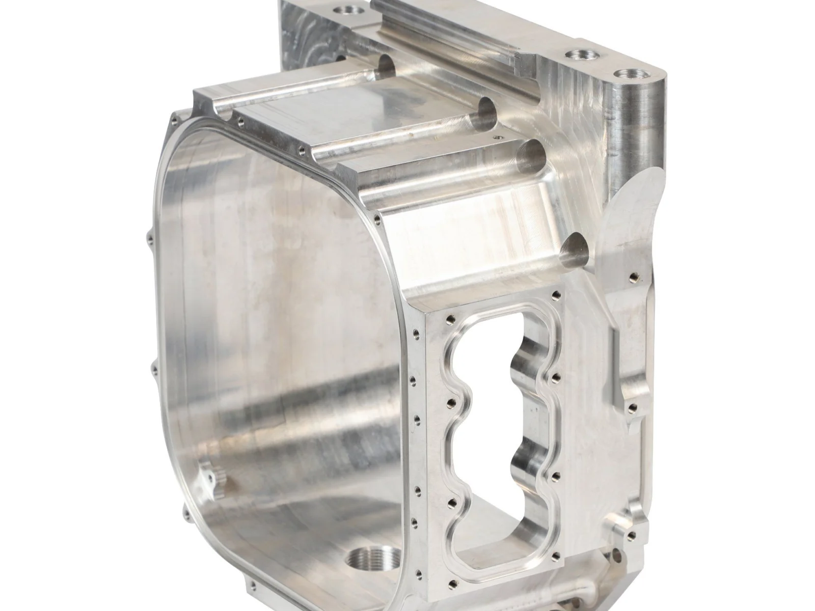
CNC milled aluminum housing with pockets, bores and tapped mounting holes
CNC spindle machining a hole feature in a machined round part

HOLES & THREADS

Drilling and secondary hole features.

Drilling creates the holes required for mounting, locating and assembly. Hole sizes, depths, thread requirements and the relation to machined datums are reviewed against the drawing. Milling, drilling and tapping are coordinated within the part route.

  • Equipment housings and covers
  • Mounting plates and brackets
  • Automation fixtures and tooling components

DESIGN FOR MILLING

Design features that stay practical to mill.

Internal corner radii

Use radiused internal corners where an end mill must reach.

Deep pockets & thin walls

Review deep pockets and thin walls for deflection and workholding.

Assembly datums

Call out the datums that control assembly fit.

Aluminum plates being pocket milled on a vertical machining center
Clamping, coolant and tool reach are planned with the part features, so pockets and faces can be milled in as few setups as possible.
Milled aluminum blocks and flange housing with threaded ports and bores

ALLOYS & FINISHES

Define the alloy, finish and mating features.

Aluminum offers an effective balance of machinability and weight for many milled parts. Stainless steel, carbon steel, brass, and engineering plastics may be more suitable for wear, corrosion, conductivity, or insulation needs.

  • As-machined, bead-blasted, anodized, plated, or coated surfaces can be specified for appearance and service conditions. Finish thickness should be considered for close-fitting features.
  • Critical bores, mounting patterns, and mating faces can be checked during the process and at final inspection against the agreed drawing.

CNC milling capability ranges

Milled parts are planned around the faces and bores that control assembly. We decide the number of setups, the fixture and the datum transfer before programming, so related features are cut from the same reference wherever the geometry allows. Typical values are listed below; the tolerance for each feature is confirmed during drawing review.

Vertical machining centers
600 to 1800 mm X travel
Gantry machining
Up to 2500 × 2000 × 900 mm
Machine accuracy
Positioning ±0.003 mm per 300 mm, repeatability ±0.0025 mm
Milled bore positions
Typically ±0.01 mm, confirmed per drawing
General tolerance
ISO 2768-m unless the drawing states otherwise
Surface roughness
Ra 1.6 µm as machined; finer surfaces by grinding
Multi-face parts
Indexed 3+2 and simultaneous 5-axis machining
Order quantity
From 1 piece to repeat batches

CNC milling FAQ

What is the largest part you can mill?

Parts up to 2500 × 2000 × 900 mm on gantry machining centers. Large frames and plates are reviewed for fixturing, stress relief and inspection access before quotation.

When is 5-axis machining worth considering for a milled part?

When bores, faces or bosses on several sides must stay aligned, or when the part has angled features and curved surfaces. Cutting them in one clamping avoids the position error that builds up across separate fixtures, although a 3-axis route with a dedicated fixture is sometimes cheaper, so both are compared when quoting.

Which materials do you mill most often?

Aluminum 6061, 6082 and 7075, stainless steel 304 and 316, carbon and alloy steels, brass, and engineering plastics such as POM and PEEK. Hardened inserts are finished by wire EDM or grinding after heat treatment.

How do you prevent thin walls and deep pockets from distorting?

We rough the part, release it from the fixture so internal stress can relax, then finish critical faces. Wall thickness, cutter reach and internal corner radii are reviewed with you during the quotation.

What should I send for a milling quotation?

A STEP model and a PDF drawing with the revision, material, quantity, finish and the datums that control assembly. An engineer replies with questions or a quotation within one business day.

LET’S TALK ABOUT YOUR PART

Send the housing or plate you are working on.

Mark the faces and bores that locate in the assembly. We will come back with the likely number of setups and the tolerances that affect the price most. Or email the drawing to info@tovilon.com.

WhatsApp