MANUFACTURING CAPABILITIES

Precision Machining for Fit-Critical Components

Drawing-led machining support for parts with critical dimensions, mating surfaces, and inspection requirements.

We aim to reply within 1 business day · Mon–Fri, China time (UTC+8).
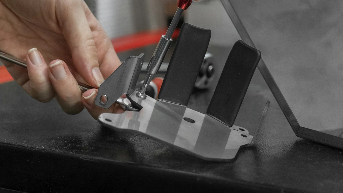
Dimensional check on a machined housing
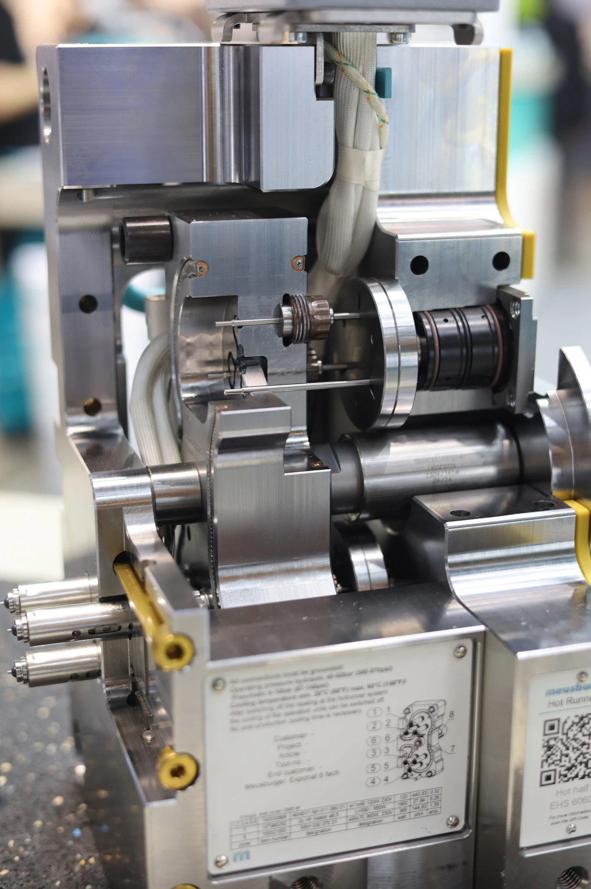
Steel mold tooling with machined cavities and locating features

PROCESS & APPLICATION

Focus precision on the features that control fit.

Precision machining begins by identifying what must be controlled for the part to work. We review datums, functional fits, material, and the inspection method before deciding where closer limits are necessary. The goal is a measurable part, not a drawing covered in unnecessary tight tolerances.

  • Alignment and locating components
  • Bearing and mating interfaces
  • Inspection-sensitive equipment parts
Discuss Your Requirements

PART PLANNING

Connect the tolerance to its measurement method.

Functional dimensions

Define datums that reflect how the part is located in the assembly.

Datum strategy

Call out critical dimensions and geometric relationships clearly.

Measurement conditions

Agree on a measurement method for features that control function.

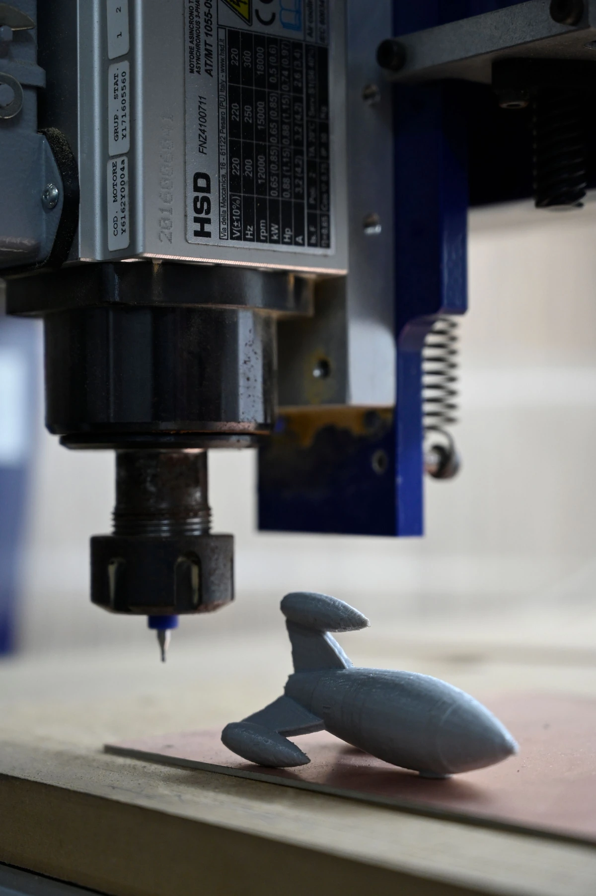
Machine spindle and cutting tool in a milling setup

MATERIALS, FINISH & ACCEPTANCE

Agree the controlled features and inspection records.

Material stability and finish affect final dimensions. Aluminum, stainless steel, alloy steel, and engineering plastics each need a different approach to workholding, cutting, and measurement.

  • Surface treatments should be reviewed before final dimensioning where coating thickness or polishing may change a functional fit.
  • Critical features can be checked during machining and at final inspection using methods appropriate to the geometry and agreed drawing.
Discuss Your Requirements

PROJECT QUESTIONS

Before you send the drawing

What makes a part a precision machining project?

It is the functional relationships and measurement requirements, not a generic tolerance number, that define the work.

Should every dimension be tightly controlled?

No. Identify the interfaces that affect performance and use practical general requirements elsewhere.

What should be marked on the drawing?

Datums, critical fits, material, finish, and any inspection evidence needed for acceptance.

ENGINEERING PLANNING REFERENCE

Put numbers on the requirements.

Industry benchmarks for preparing your RFQ. The drawing review confirms the manufacturing route, capability and delivery schedule.

±0.10 mm

General metal features

A useful general-tolerance discussion point. State the drawing standard and dimension range; one blanket value does not cover every feature.

±0.01 mm

Selected critical features

A precision target for review, not a default for the whole part. Material, geometry, setup, temperature and measurement method matter.

3 / 4 / 5

Axis strategy

Compare 3-axis, indexed and simultaneous machining around tool access and datum control. The quotation confirms the proposed route.

1 / 10 / 100

Quantity comparisons

Use these RFQ quantities to compare prototype, pilot and repeat-part pricing. These are planning scenarios, not a stated MOQ.

5–10 days

Prototype schedule discussion

An initial manufacturing-window assumption for simple, stock-material parts. Finishing, inspection, capacity and shipping require separate confirmation.

Ra 3.2 µm

Surface requirement example

An as-machined roughness discussion point. Identify functional faces; sealing, bearing and cosmetic surfaces may need different requirements.

Send overall dimensions and critical features for feasibility review. Production lead time starts from the agreed release conditions; transit time is separate.

LET’S TALK ABOUT YOUR PART

Bring your drawing.
Define the next step.

Material, quantity, finish and critical features — start with what you know.

Call UsWhatsApp