METAL 3D PRINTING · TECHNICAL ARTICLE
SLM Porosity: How Laser Power, Scan Speed, Layer Thickness and Powder Affect Part Density
By Martin Ji, TOVILON Precision ·
A laser melted part can look perfect on the build plate and still carry pores that leak, crack or open up during machining. Here is where those pores come from in selective laser melting, which settings move density, and what HIP and CNC finishing can and cannot fix.
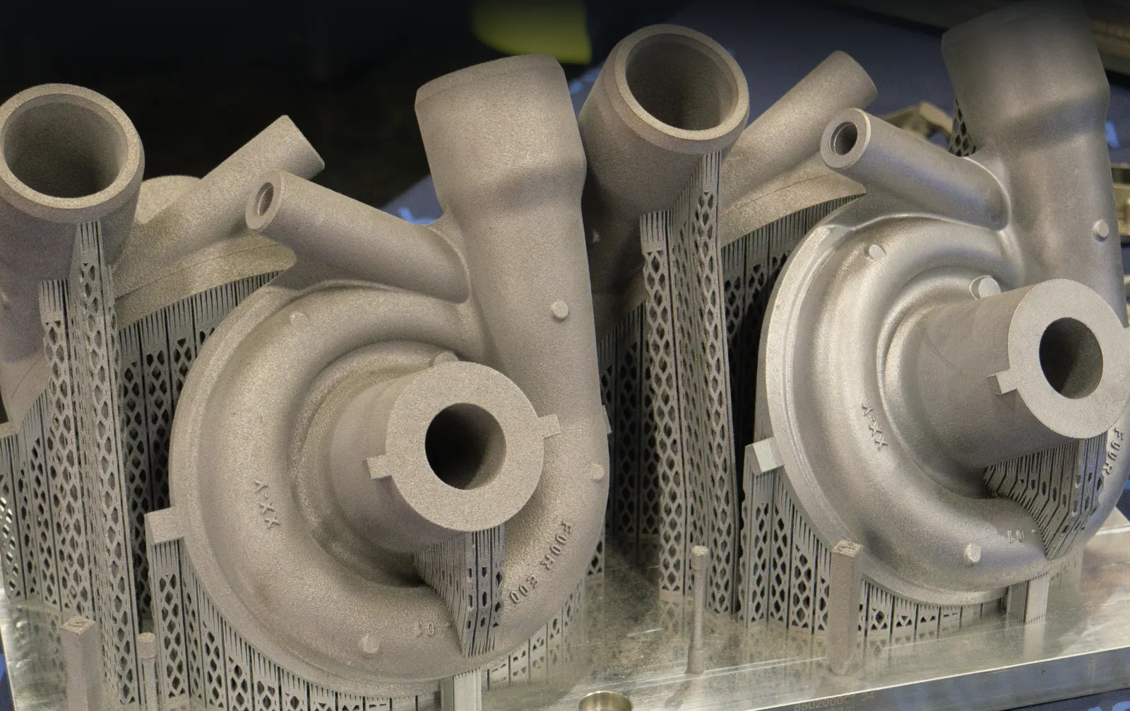
Short answer. Porosity in selective laser melting (SLM, also called laser powder bed fusion or DMLS) is mainly set by how much laser energy reaches each layer of powder. Too little energy leaves lack of fusion pores. Too much drives the melt pool into keyhole mode and traps gas. Powder that carries moisture or gas adds small round pores on top.
- Laser power, scan speed, hatch spacing and layer thickness have to be tuned as one set.
- Developed parameters routinely give more than 99.5% relative density in 316L, AlSi10Mg and Ti-6Al-4V.
- Dry, well sieved powder with a controlled reuse history is part of the process, not an extra.
- HIP closes internal pores but not pores that reach the surface.
- CNC machining delivers fits, threads and sealing faces. It does not remove internal pores.
Most metal printing questions we receive start the same way: can this part be printed? For SLM the answer is usually yes. The more useful question is how dense the printed material will be, because that decides whether a manifold holds pressure, a bracket survives vibration or an O-ring face seals after machining. Getting the shape right is the easy half of the job. Density is where the engineering sits.
What porosity looks like in an SLM part
SLM spreads a thin layer of metal powder, commonly 30 to 60 µm thick, and melts the cross section with a focused laser. Each scan track has to fuse with the track beside it and with the layer underneath. Pores appear wherever that does not happen cleanly, and they fall into three recognizable types.
| Pore type | What it looks like | Usual cause |
|---|---|---|
| Lack of fusion | Irregular, flat voids between tracks or layers, sometimes with unmelted powder inside | Energy too low, hatch spacing too wide or layer too thick for the laser power |
| Keyhole | Round pores near the bottom of melt tracks | Energy too high, so the melt pool becomes deep and unstable and collapses around a vapor cavity |
| Gas | Small, spherical pores spread through the material | Gas trapped in atomized powder, or moisture on the powder releasing hydrogen, which is a known issue with aluminum alloys |
The type matters more than the percentage. A part at 99.5% density with small, isolated gas pores behaves very differently from one at the same density with a sheet of lack of fusion defects lined up across a load path. Flat, sharp edged voids are the ones that start fatigue cracks and connect into leak paths.
Which laser settings control density?
Four settings define how much energy each volume of powder receives: laser power (P), scan speed (v), hatch spacing between tracks (h) and layer thickness (t). Engineers often combine them into a volumetric energy density, E = P / (v × h × t), in J/mm³. It is a useful starting point for comparing parameter sets, but it is not the whole story: two combinations with the same energy density can melt very differently.
Laser power and scan speed
These two set the size and stability of the melt pool. Slow the laser down or raise the power and the pool gets deeper and wider. Within the right window that closes the gaps between tracks. Go past it and the pool tips into keyhole mode, where the metal partly vaporizes, a deep cavity forms and gas gets trapped as the cavity collapses. King and colleagues documented this transition clearly in stainless steel. Go too fast or too cold and the tracks stop overlapping, which is the start of lack of fusion.
Hatch spacing
Hatch spacing is the distance between neighboring scan tracks. If it is wider than the melt pool, ridges of partly melted powder remain between tracks and turn into lack of fusion voids in the next layer. If it is much narrower, the same material is remelted several times, which costs build time and adds heat without improving density.
Layer thickness
Thicker layers build faster, which is why they look attractive on a quotation. The laser then has to melt through more powder and into the previous layer. Without a matching increase in energy, the bond between layers weakens and lack of fusion pores appear in planes parallel to the build plate. Those planar defects are particularly bad for parts loaded along the build direction.
Contours, scan strategy and orientation
Density is not uniform through a part. Most machines scan the outline of each layer with a separate contour pass, and those settings control the dense skin that later carries the machined faces. Downward facing surfaces and overhangs sit on loose powder, overheat more easily and are rougher and more porous. Rotating the scan direction between layers spreads defects so they do not stack up. Build orientation therefore decides where the densest material ends up, and we choose it with the critical faces of the drawing in mind.
Research on AlSi10Mg by Aboulkhair and colleagues showed how strongly porosity responds to scan speed and scan strategy, with a modified strategy that passes the laser over each layer twice giving the lowest pore content in their tests. The broader lesson holds across alloys: density comes from a balanced parameter set developed for that alloy and machine, not from pushing one setting to its limit.
Why powder condition matters as much as the laser
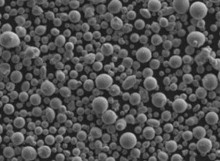
The laser can only melt what the recoater lays down. Spherical, gas atomized powder in a controlled particle size range spreads into an even layer with few gaps. Irregular particles, satellites stuck to larger particles or too many fines make the layer patchy, and patchy layers melt unevenly.
Moisture is the hidden one. Aluminum powders in particular pick up moisture from the air, and the hydrogen released during melting becomes gas porosity. Drying powder before use and storing it sealed are routine controls for AlSi10Mg. Reused powder also changes over cycles: it picks up oxygen, collects spatter and coarsens. Sieving between builds and tracking how many times a batch has been reused keep that drift under control.
After the build: stress relief, HIP and heat treatment
SLM parts come off the machine with high residual stress, so stress relief on the build plate is normal before parts are cut off. For pressure retaining or fatigue loaded parts, hot isostatic pressing (HIP) applies high temperature and gas pressure at the same time and collapses most internal pores.
HIP has two limits worth knowing. It cannot close pores that connect to the surface, because the pressurizing gas simply enters them. And it changes the microstructure, so the heat treatment route and the required strength, hardness or ductility have to be agreed before the build, not after.
How to check density on a printed part
- Archimedes density on parts or test coupons from the same build gives a quick bulk value.
- Metallographic sections of a sample part or coupon show pore type, size and position.
- CT scanning finds internal voids without cutting the part, which suits high value or safety related components.
- Pressure or leak testing after machining is the direct check for manifolds and housings.
Inspection should match the risk. A fixture bracket may only need coupons from the build. A manifold that carries pressure deserves a leak test on every part.
Can CNC machining fix porosity in a printed metal part?
No. CNC machining is the right way to bring a printed part to drawing tolerance: accurate bores, true threads, flat sealing faces and the surface finish that SLM cannot give on its own. But machining only removes surface material, so it does nothing about pores inside the part, and it can open a pore that sat just under the skin and turn a sealing face into a leak path.
Two habits help. Leave machining stock on every functional face, so the cutter finishes in the dense contour and core material rather than the rougher skin. And orient the part so sealing faces and bores are built where density is highest, not on downward facing surfaces. Our AlSi10Mg manifold example follows exactly this route: printed, stress relieved, then CNC finished on the sealing faces and ports.
How is SLM different from extrusion based metal printing?
Extrusion based metal printing (metal FDM or FFF) deposits a metal powder and binder mix through a nozzle, then removes the binder and sinters the part in a furnace. There, density depends on printing speed, nozzle size, deposition pressure, debinding and sintering, and published 316L results sit around 95% density with about 20% shrinkage. SLM has no binder and no sintering step, and it reaches higher density. Settings and conclusions do not transfer between the two processes, so advice about nozzle size says nothing about a laser melted part.
Choosing the route for a metal part
Start from what the part has to do, then pick the process. Before we recommend SLM, CNC machining from solid or a combination, we ask:
- Does the part hold pressure or seal a fluid?
- Is it loaded in fatigue or mainly statically?
- Which features are fits, threads or sealing faces that will be machined?
- Does the geometry need internal channels or lattices that only printing can make?
- How many parts are needed now, and how many later?
For a printed part, send the alloy, quantity and the features that matter for function with the model; the review then covers SLM, CNC machining or both. See 3D printing options and the inspection process for how density and finished features are checked.
Frequently asked questions
What causes porosity in SLM metal parts?
Three mechanisms cover most cases. Lack of fusion pores form when the laser delivers too little energy or the tracks are spaced too far apart, so neighboring tracks and layers do not fully melt together. Keyhole pores form when the energy is too high and the deep melt pool collapses and traps gas. Gas pores are small, round voids from gas or moisture carried in by the powder.
Which SLM parameters control part density?
Laser power, scan speed, hatch spacing and layer thickness. Together they set the energy delivered to each unit volume of powder. Density is highest inside a process window: below it, lack of fusion appears; above it, keyhole pores appear. Contour scans, scan strategy and build orientation then decide how dense the outer skin and overhangs are.
How dense can SLM parts be?
With developed parameters, common alloys such as 316L, AlSi10Mg and Ti-6Al-4V are routinely built above 99.5% relative density. The remaining pores are small and mostly closed. Hot isostatic pressing can close most of those internal pores on critical parts.
Does HIP remove all porosity?
No. HIP closes internal pores that are sealed from the surface. Pores connected to the surface stay open because the pressurizing gas enters them. HIP also changes the microstructure, so heat treatment and the required properties should be agreed before the build.
Can CNC machining fix porosity in a printed metal part?
No. Machining brings bores, threads and sealing faces to drawing tolerance and finish, but it only removes surface material. It can also open a pore that sat just under the surface, so the printed material has to meet the density requirement on its own.
References
- King, W. E., Barth, H. D., Castillo, V. M. et al. Observation of keyhole-mode laser melting in laser powder-bed fusion additive manufacturing. Journal of Materials Processing Technology 214(12), 2915-2925, 2014. OSTI record.
- Aboulkhair, N. T., Everitt, N. M., Ashcroft, I. and Tuck, C. Reducing porosity in AlSi10Mg parts processed by selective laser melting. Additive Manufacturing 1-4, 77-86, 2014. doi:10.1016/j.addma.2014.08.001.
- Thompson, Y., Gonzalez-Gutierrez, J., Kukla, C. and Felfer, P. Fused filament fabrication, debinding and sintering as a low cost additive manufacturing method of 316L stainless steel. Additive Manufacturing 30, 100861, 2019. doi:10.1016/j.addma.2019.100861.