ADDITIVE MANUFACTURING
Metal and Polymer 3D Printing with CNC Finishing
Metal, nylon, resin and ceramic 3D printing, with CNC finishing of the faces that have to fit. The right process usually follows from three things: the material the part needs, the load or heat it sees, and how many you need.
Request a Quote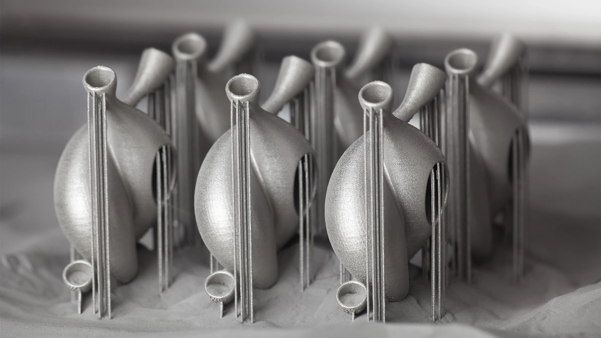
Find the printing process for your part
The short version first. The sections below go through each process family.
| Process | Good at | Watch for | Consider instead |
|---|---|---|---|
| SLA | Smooth surfaces and fine detail: appearance models, covers, clear parts | Standard resins are more brittle than nylon and soften at lower temperatures; tough and high temperature resins narrow the gap | MJF or SLS for parts that carry load or heat |
| DLP | Very small, finely detailed resin parts | Small build area | SLA for larger parts |
| MJF | Functional nylon parts and small batches. No supports, so many parts fit in one build. | Typical as printed surface is gray and slightly grainy | SLA when a smooth cosmetic surface matters |
| SLS | Nylon and flexible TPU parts without supports | Typical as printed surface is rougher and slightly porous. Large flat parts can warp. | Injection molding once the volume pays for a tool |
| FDM | Fit checks, jigs and concept models at low cost, including larger parts | Visible layer lines. Strength between layers depends on material and settings, but is lower than along them. | SLA or CNC machining for fine detail or tight tolerances |
| SLM | Dense metal parts with internal channels, lattices or several parts merged into one | Supports, residual stress and rough as printed surfaces. Properties depend on the alloy and heat treatment, and fits and sealing faces typically need CNC finishing. | CNC machining for simple prismatic or turned parts |
| Ceramic | Small parts that need heat resistance, wear resistance or electrical insulation | Shrinkage during sintering, so feasibility is checked part by part | A metal or engineering plastic part, when the application allows |
These are general tendencies. The exact material grade, machine and post processing change the result, so the route for a specific part is confirmed on the quotation.
Metal printing
SLM for complex metal geometry, with machining planned for the interfaces that control fit.
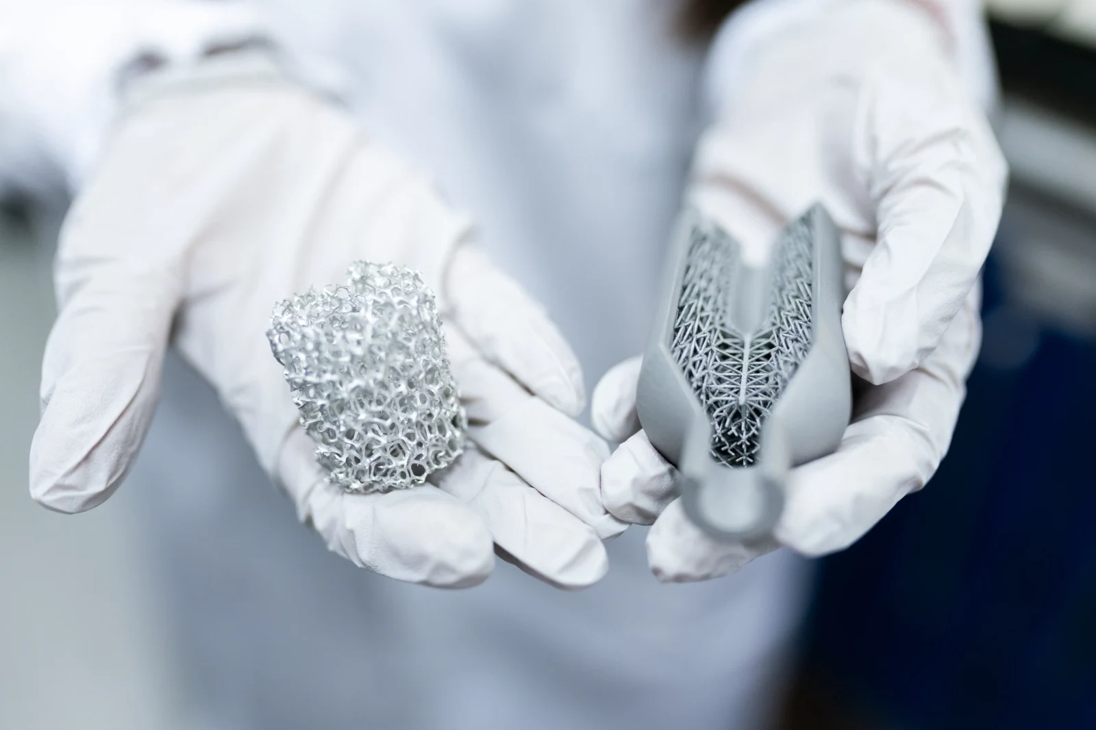
SLM: metal powder-bed fusion
Metal components with complex internal or lightweight geometry.
Review build orientation, supports, distortion, machining allowance and powder removal access.
Aluminum, titanium, stainless steel and other metal grades are reviewed for the selected build route. Plan support removal, stress relief where required, and CNC finishing of mating bores, threads and datum faces.
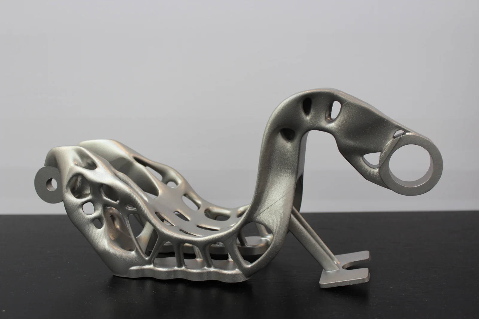
SLM mounting and locating parts
Mounting holes and locating faces are usually printed with stock left on them and finished by CNC, so the machined faces share one datum.
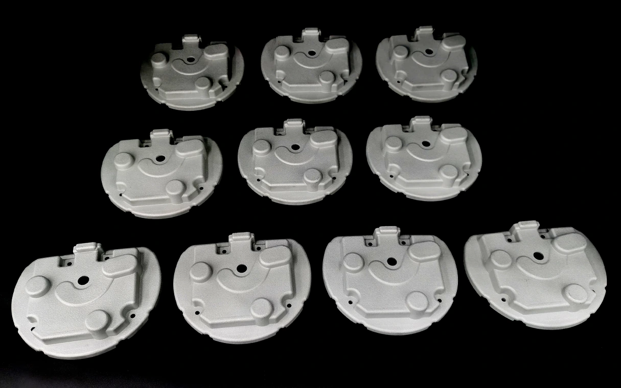
SLM mechanical housings
Internal cavities that could not be machined, with the bores and datum faces machined after printing.
Engineering polymer printing
MJF, SLS and FDM for functional housings, ducts, fixtures and development parts.
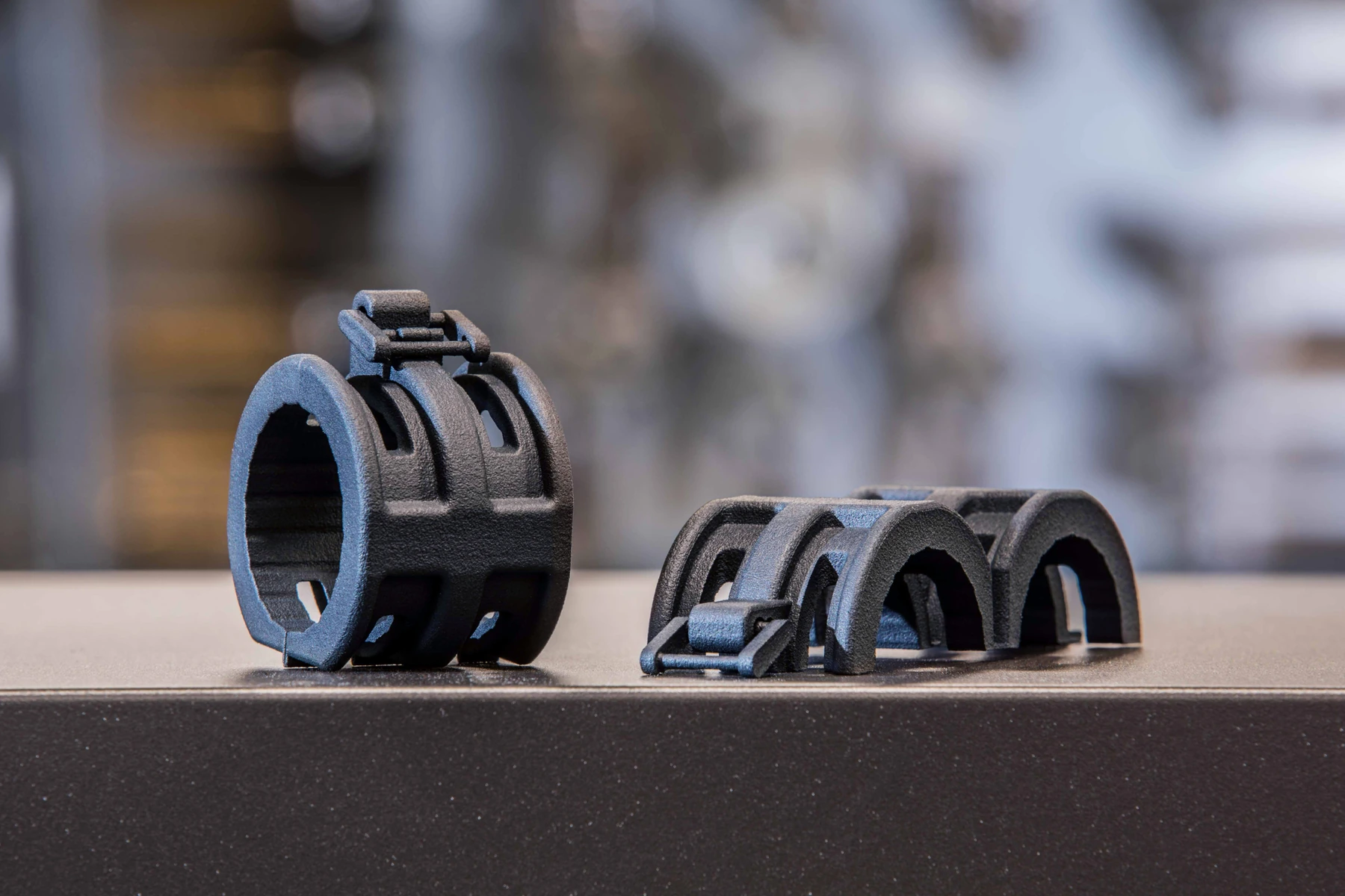
MJF and SLS: powder-bed nylon
Nylon housings, clips, ducts and small batches with complex shapes and internal features.
Parts come out slightly grainy and porous. Snap fits and mating clearances usually need a little more room than in a molded part, and closed cavities need a hole to let the powder out.
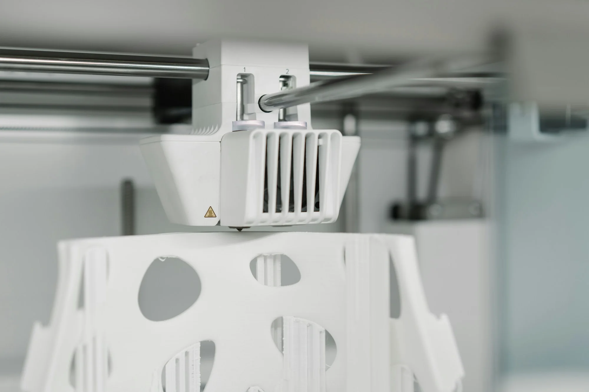
FDM: fused deposition modelling
Fit checks, concept models and suitable polymer components.
Parts are weakest between layers, so the build is oriented with the main load running along the layers rather than across them.
Resin printing
SLA and DLP for detailed prototypes, covers and small-feature components.
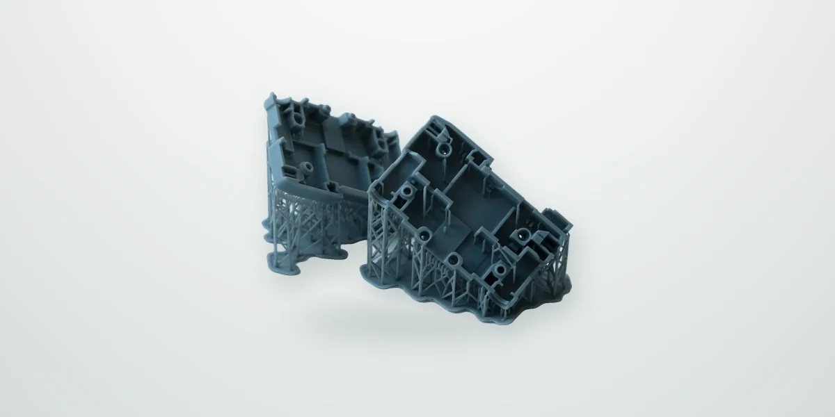
SLA: stereolithography
Resin models, housings and detailed prototypes.
Support marks are sanded off and hollow parts need drain holes. Standard resins soften at much lower temperatures than nylon, so SLA suits appearance and fit checks more than load or heat.
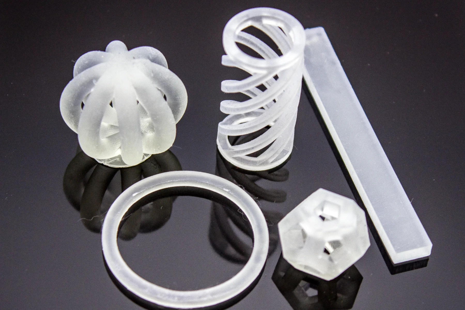
DLP: digital light processing
Fine-detail resin components and small features.
The build area is small, which suits small, finely detailed parts. Larger resin parts go to SLA.
Ceramic printing
Specialist ceramic components need a defined debinding, sintering and acceptance route.
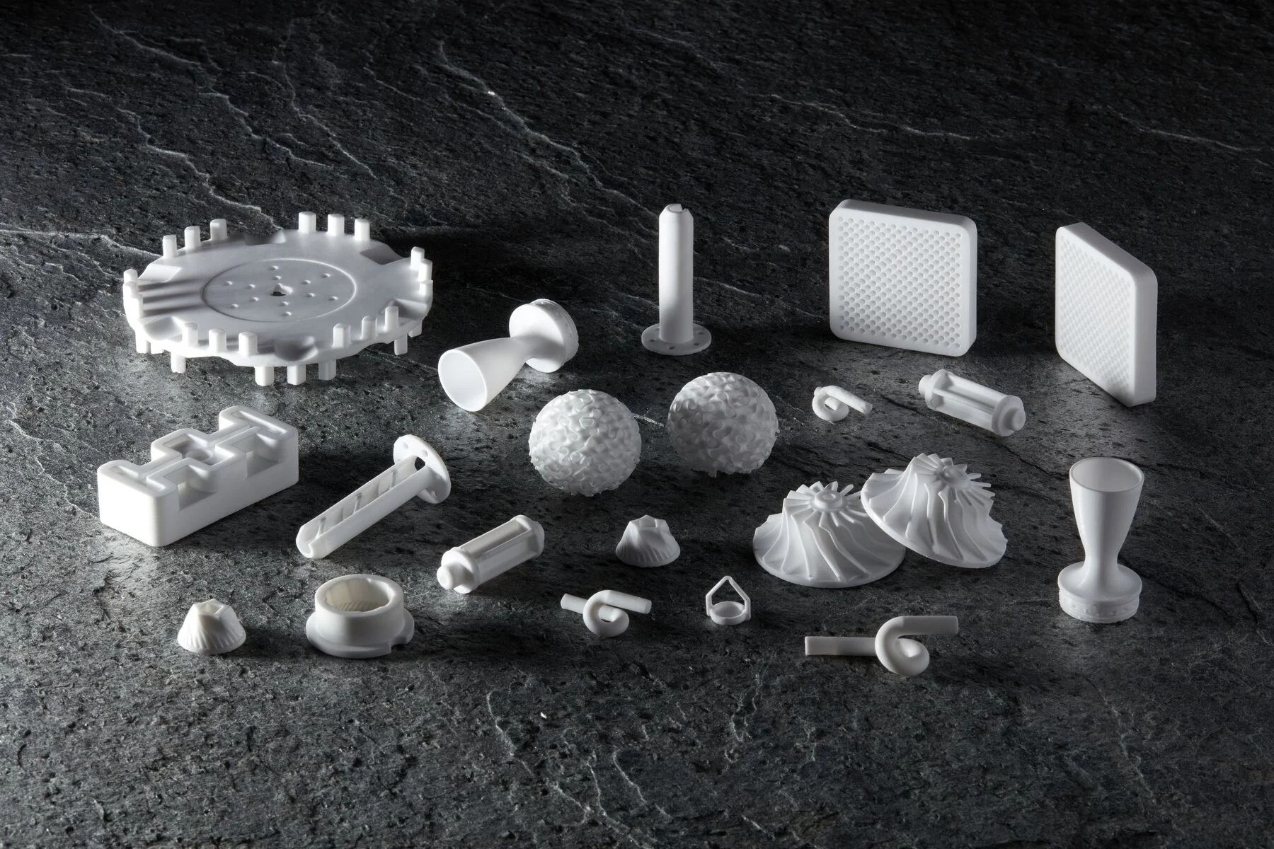
Ceramic printing
Specialist ceramic components and development parts.
Ceramic parts shrink during debinding and sintering, so feasibility and tolerances are reviewed part by part.
Material selection at a glance
| Material family | Printing routes | What to specify |
|---|---|---|
| Metals | SLM | Aluminum, titanium, 316L stainless steel, high-temperature alloys, tool steels and copper alloys for project review. Define heat treatment, machining allowance and final acceptance. |
| Engineering polymers | MJF / SLS / FDM | PA11, PA12, glass-filled nylon, TPU, PP-like options and other process-compatible polymers. Specify loading, stiffness, moisture exposure and temperature. |
| Resins | SLA / DLP | Standard, clear, tough and high-temperature options. Confirm the material datasheet, curing, appearance and intended use. |
| Ceramics | Specialist ceramic printing | Confirm formulation, shrinkage, debinding and sintering. Material and process suitability are reviewed individually. |
Plan printing, finishing and inspection together
1. Review the model
Check wall thickness, overhangs, load direction and access for removing powder or supports. Identify mating and cosmetic surfaces before the build.
2. Define finishing
Agree cleaning, support removal, curing or heat treatment where required. Printed metal bores, threads and datums may need CNC finishing.
3. Agree acceptance
State which dimensions apply after finishing. Confirm sample approval, material evidence and dimensional reporting with the quotation.
For difficult finishing access, review five-axis machining. See inspection and acceptance planning for the required records.
Send a complete 3D printing inquiry
- Provide a model and, where dimensions determine acceptance, a dimensioned drawing.
- State the process or request advice; identify material, quantity and production stage.
- Describe loading, temperature, appearance and the purpose of the prototype or production component.
- Identify finishing, CNC-machined interfaces, inspection records and requested date.
The RFQ form takes STL, 3MF and OBJ files directly, as well as STEP, PDF and ZIP, up to 30 MB per file and any number of files. For larger models, put a secure file link in the project details. Discuss an NDA before releasing confidential models.
Request a QuoteRelated engineering guides
Part examples made to drawing: an SLM printed manifold.
3D printing FAQ
Which 3D printing processes are available?
SLA and DLP resin, MJF and SLS nylon, SLM metal, FDM and ceramic printing. The process is chosen for the part function, material, size and surface requirements.
Can metal 3D printed parts be CNC finished?
Yes. Sealing faces, bores, threads and other functional interfaces are machined after printing to reach drawing tolerances. Machining does not close internal pores, so the printed material must meet the density requirement on its own.
When is metal 3D printing a better choice than CNC machining?
When the part has internal channels, lattice structures or several components consolidated into one, or when only a few complex parts are needed. For simple prismatic or turned parts, CNC machining is usually faster and more accurate.
Do you print small quantities?
Yes. Prototypes and small batches are quoted from 1 piece, and printed parts can be combined with machined parts in the same order.