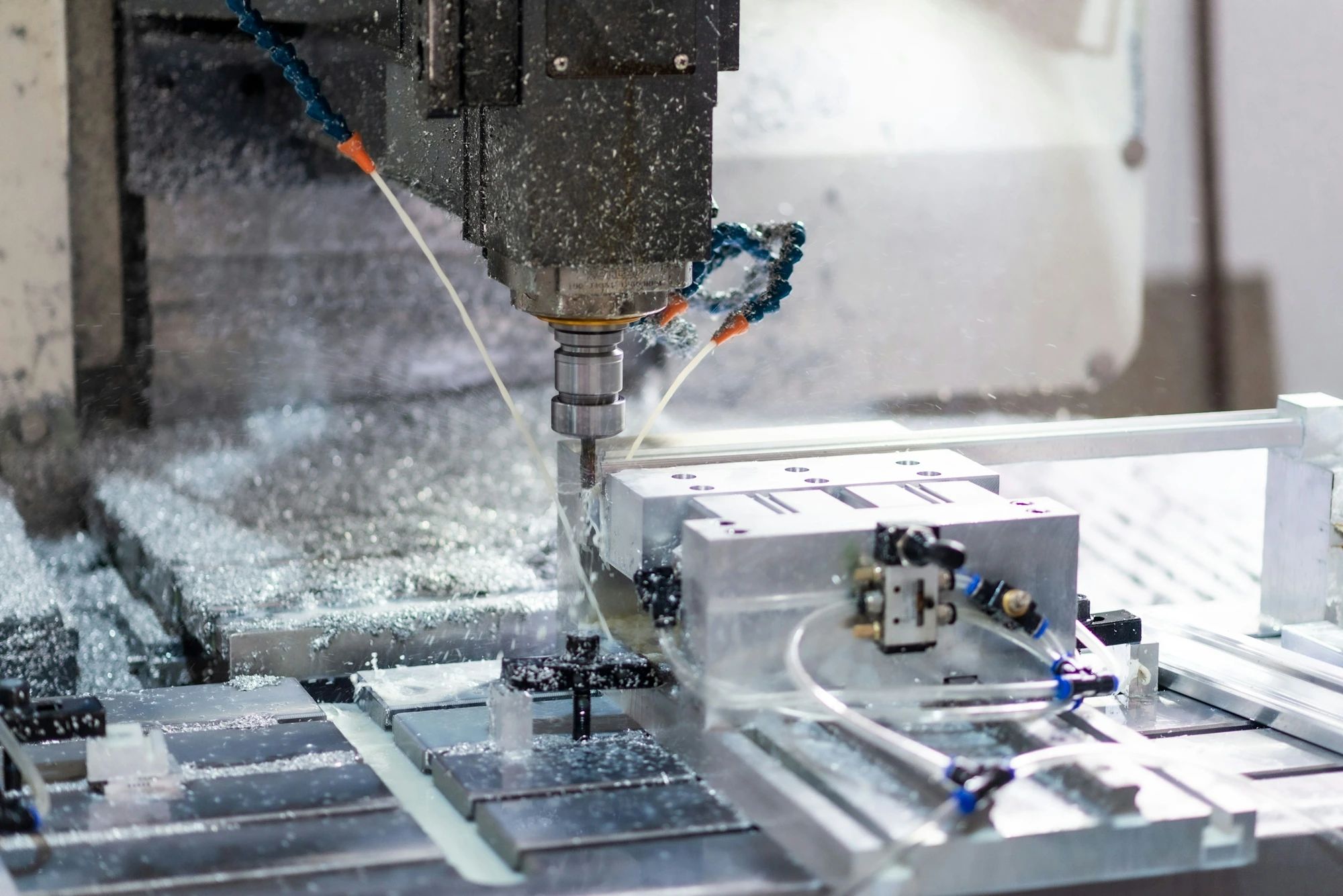
A deep pocket is a familiar CNC milling feature. So is a drilled hole, a thin wall or a precision bore. What makes a component difficult to manufacture is often the way these features interact.
Machining a pocket may leave a thin section that is more susceptible to deflection. A hole may need to be positioned relative to a face that is machined in a separate setup. Finishing one feature can also remove material that previously supported another.
These relationships affect tool access, workholding, machining sequence and inspection. They are also easy to overlook when a drawing is reviewed dimension by dimension.
For custom CNC parts, the real manufacturing challenge often lies in the connections between features.
A feature cannot always be planned in isolation
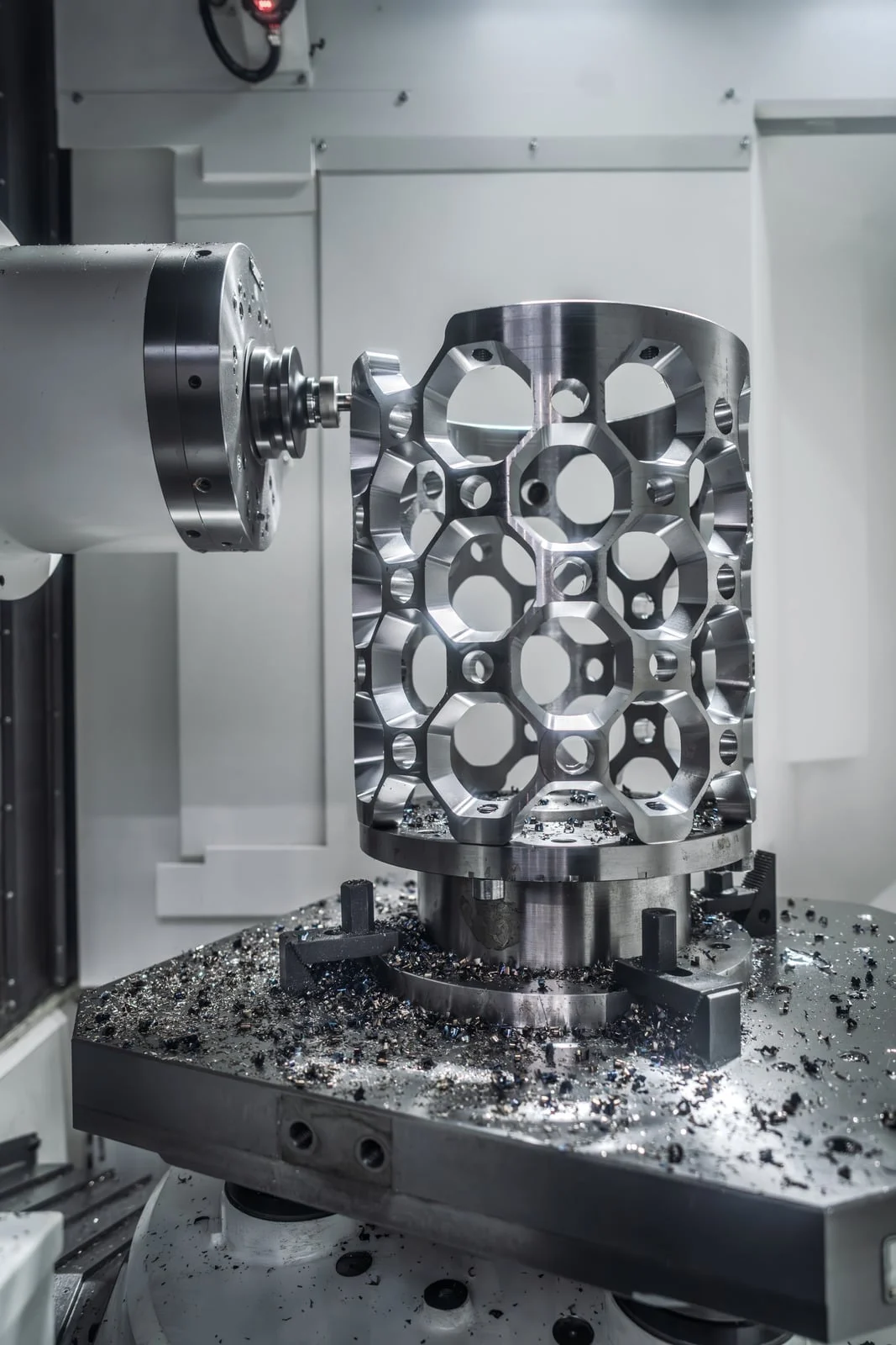
Manufacturing research has examined how the geometry of holes, slots and pockets creates dependencies between machining operations. One study on manufacturing-feature interactions developed methods for representing alternative machining sequences and identifying constraints between features [1].
The practical idea is straightforward: the order in which features are machined can affect which operations remain possible, how the workpiece is positioned and how much material supports the remaining geometry.
A pocket may be accessible from above, but a cross-hole could require a different orientation. A mounting face may serve as a datum for a precision bore, making the relationship between those features important to the setup and inspection plan. Where multiple operations use different datums, the accumulated effects of repositioning the workpiece also deserve consideration.
This is why counting features provides a poor measure of machining difficulty. A part with many accessible holes and simple faces may be easier to manufacture than a smaller component with one deep cavity, restricted tool access and several tightly related interfaces.
The manufacturing route has to account for the geometry as a whole.
Removing material changes the part being machined
Thin-wall components illustrate this interaction particularly clearly.
As material is removed, the stiffness of the remaining workpiece changes. A wall that was supported by surrounding material during roughing may become more flexible during finishing. Cutting forces can then cause deflection, while vibration can affect surface finish and geometric accuracy.
A 2021 review in the Journal of Manufacturing Processes examined chatter and geometric errors in thin-wall machining, including the mechanisms behind vibration and workpiece deformation and the methods used to predict or reduce them [2].
For the manufacturing engineer, this has a direct implication for machining sequence. The final wall thickness matters, but so does the geometry left around the wall during each operation. Tool engagement, cutter overhang, fixture support and the amount of material removed in earlier passes influence the conditions encountered during finishing.
The drawing should therefore be reviewed with the material-removal sequence in mind. A thin wall next to a deep pocket may require a different approach from an equally thin wall supported by a solid section. Treating both features independently misses the interaction that creates the difficulty.
The datum relationship can be more demanding than the dimension
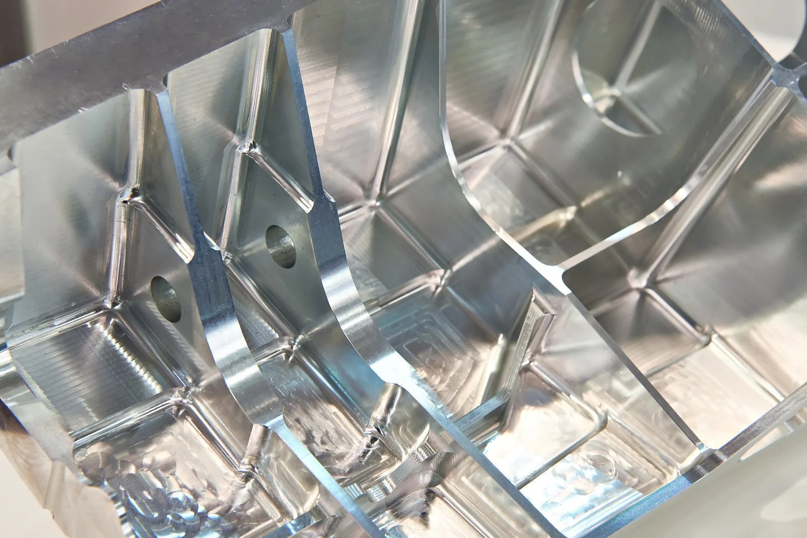
A precision bore is often specified by diameter and positional tolerance. Its manufacturing requirements may also depend on its relationship to a mounting face, another bore or a shaft axis.
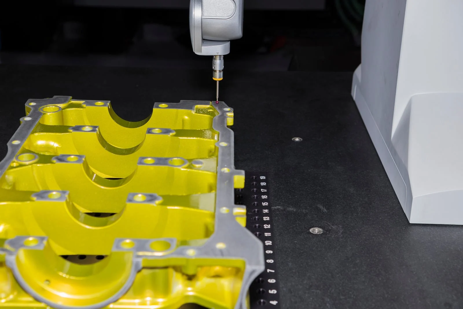
These relationships influence setup planning. If the bore and its reference face are machined in separate operations, the method used to locate the workpiece becomes important. If several bores must align across an assembly, the inspection strategy needs to establish the relevant geometric relationships, not merely confirm each diameter.
Thermal behaviour adds another consideration for demanding applications. A review of spindle thermal-error compensation published in the International Journal of Machine Tools and Manufacture examined temperature measurement, thermal-error modelling and compensation methods [3]. This research is relevant when thermal displacement affects the machine’s machining reference and, consequently, the dimensions being produced.
In practice, thermal analysis should follow an identified dimensional concern. Where measurements show that machine warm-up affects a critical feature, the machining and inspection conditions can be reviewed. Where the effect is insignificant relative to the tolerance, additional compensation may not be justified.
The objective is to understand the source of the dimensional requirement and select a manufacturing and inspection approach that addresses it.
What makes a CNC part expensive to manufacture?
Feature interactions can introduce extra setups, specialised tooling, more demanding workholding or additional inspection. These costs do not necessarily follow the overall size of the component.
A small part with a deep internal feature and a tightly positioned cross-hole may require more planning than a larger part with open, easily accessible surfaces. Likewise, a thin-walled component may need a carefully sequenced machining strategy even when the total volume of material removed is modest.
For OEM purchasing teams, this explains why the information accompanying a quotation matters. A 3D model communicates geometry, while a drawing defines dimensions, tolerances, datums and other acceptance requirements. Material, quantity, finishing and critical interfaces complete the picture needed to assess a manufacturing route.
At TOVILON, reviewing these details is part of evaluating custom CNC machining requirements for robotics, industrial automation and industrial equipment components. Deep pockets, thin sections, intersecting features and relationships between precision bores and mounting faces are useful areas to clarify early, because they can influence both the proposed process and the inspection requirements.
For a component under development, a current STEP model and dimensioned drawing provide a practical starting point for discussing these constraints. You can find more information on TOVILON’s CNC milling services or submit your component requirements through the quotation page.
References
[1] Sormaz, D. N., and B. Khoshnevis. “Modeling of Manufacturing Feature Interactions for Automated Process Planning.” Journal of Manufacturing Systems, 19(1), 28 to 45, 2000. https://doi.org/10.1016/S0278-6125(00)88888-3
[2] Wu, G., G. Li, W. Pan, I. Raja, X. Wang, and S. Ding. “A State-of-Art Review on Chatter and Geometric Errors in Thin-Wall Machining Processes.” Journal of Manufacturing Processes, 68, 454 to 480, 2021. https://doi.org/10.1016/j.jmapro.2021.05.055
[3] Li, Y., W. Zhao, S. Lan, J. Ni, W. Wu, and B. Lu. “A Review on Spindle Thermal Error Compensation in Machine Tools.” International Journal of Machine Tools and Manufacture, 95, 20 to 38, 2015. https://doi.org/10.1016/j.ijmachtools.2015.04.008