METAL 3D PRINTING · TECHNICAL ARTICLE
Machining SLM Printed Metal Parts: Supports, Datums and Which Features to Finish
By Martin Ji, TOVILON Precision ·
A small metal part can have a shape that only a printer can make and a slot or bore that only a machine tool can hold. Getting both on the same part comes down to three decisions made before the build: which faces get machined, how the part is held while they are cut, and where the machine takes its zero from.
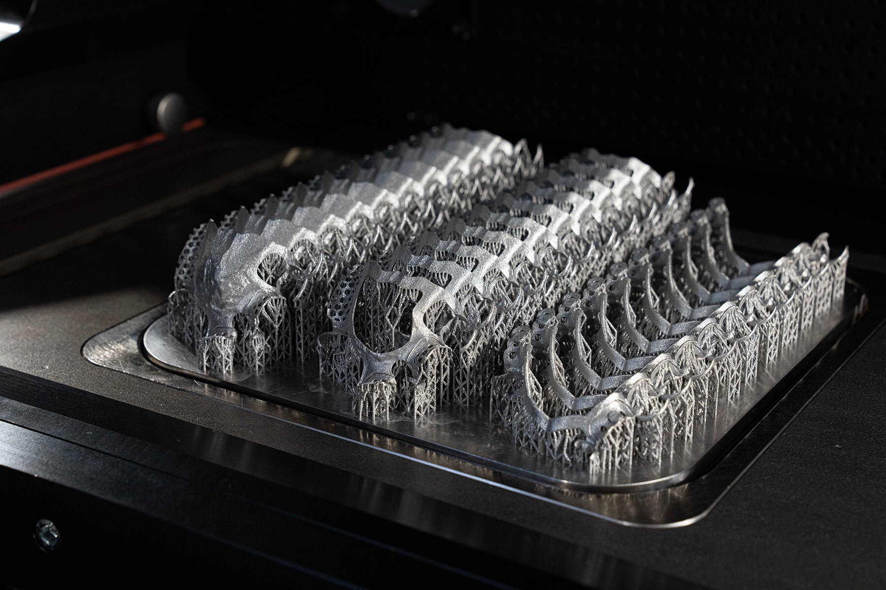
Short answer. Print the geometry, then machine only the features that decide fit and function.
- Mark the machined faces on the drawing before the build, so stock is added there and nowhere else.
- Small parts are often machined while still on the build plate. The supports then work as the fixture and have to be designed for cutting loads as well as for printing.
- The machine’s zero comes from reference features printed on the plate, confirmed with a trial cut before the finishing pass.
- Stress relieve before the parts come off the plate, or the machined features can move afterwards.
- If a part is mostly prismatic and easy to reach, machining it from solid bar is usually cheaper.
Selective laser melting (SLM), also called laser powder bed fusion, builds a part from metal powder one layer at a time. It handles thin curved walls, internal channels and lattice infill that would take hours of 5-axis work or could not be cut at all. What it does not give you is a reamed bore or a slot that a key slides into. Those still come from a cutting tool, and the way the printed part is prepared for that step decides whether the machined features end up where the drawing puts them.
What an as-built SLM part gives you
Straight off the printer, a part carries the marks of the process: partly fused powder on the surface, visible layer lines and stair-stepping on shallow slopes. Roughness on upward facing surfaces is commonly somewhere around Ra 6 to 15 µm, and downward facing surfaces that were built over supports are noticeably worse. Dimensional accuracy on small features is typically in the order of ±0.1 mm, and it shifts with orientation, wall thickness and residual stress.
For an outer shell or a cooling channel that is usually fine. For a bearing seat, a dowel hole or a slot that locates a mating part, it is not, and blasting or polishing will make the surface look better without moving the feature any closer to size.
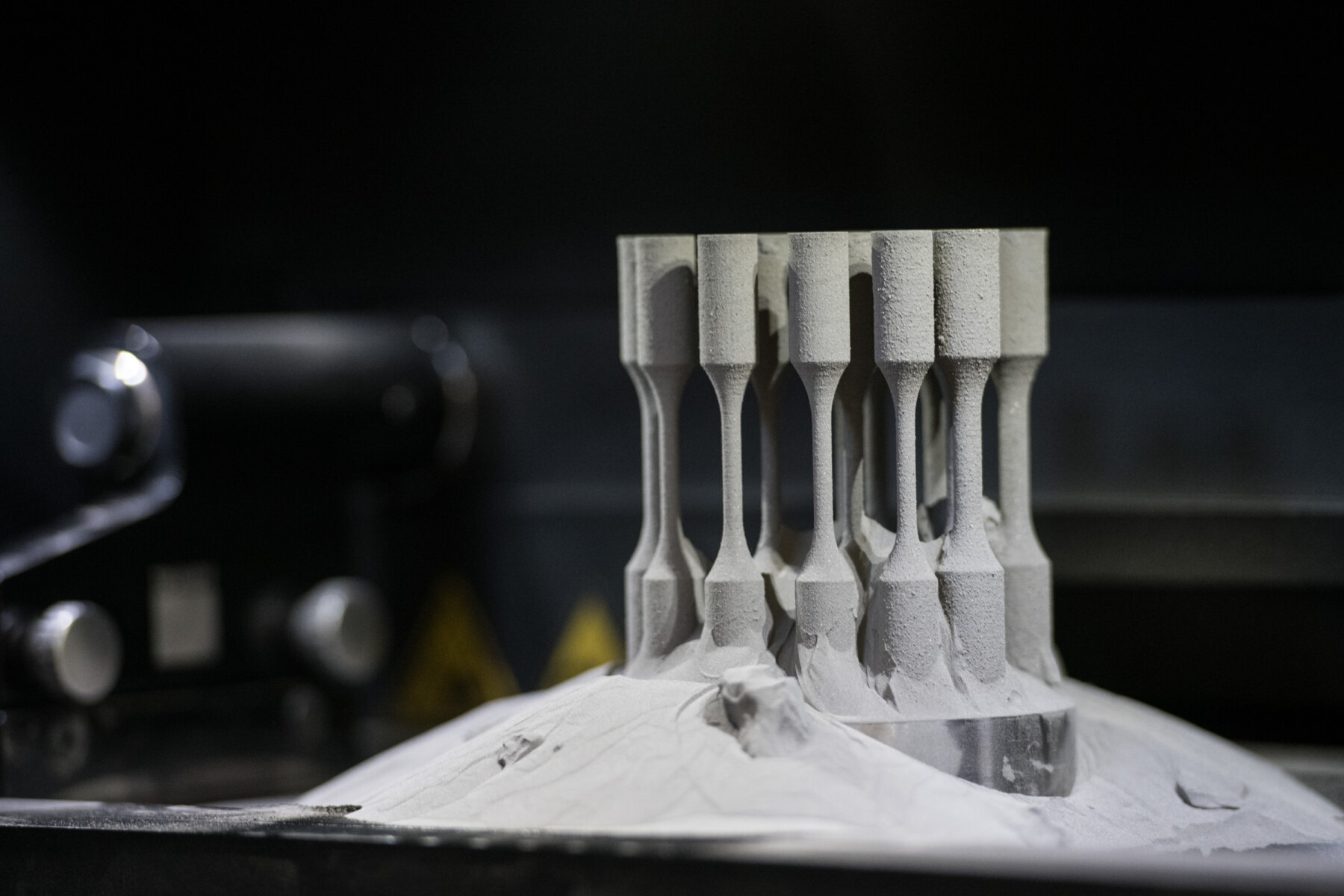
So the first job on a hybrid part happens on the drawing, not the machine: going face by face and deciding what stays as printed.
| Feature | Usually left as printed? | Typical finishing |
|---|---|---|
| Curved outer shell, ribs, lattice infill | Yes | Bead blast, or polish if it is a cosmetic face |
| Internal cooling or fluid channels | Yes | Abrasive flow or flushing if roughness matters |
| Bearing bores, locating and dowel holes | No | Bored or reamed after printing |
| Slots and keyways with a sliding fit | No | Milled to size |
| Flange, sealing and mounting faces | No | Face milled for flatness and finish |
| Threads | Rarely | Drilled undersize when printed, then tapped or thread milled |
Add stock only where it will be cut
Once the machined faces are known, the CAD model for printing is changed to suit them. Faces that will be cut get extra material, commonly 0.3 to 0.5 mm on small parts, enough to clean up the as-built surface without making the cutter work through a thick skin. Holes that will be reamed are printed undersize. Everything else stays at nominal so it does not need touching.
Build orientation is chosen with the same faces in mind. A sealing face that is printed facing down sits on supports and comes out rough, so it either needs more stock or the part is turned so that face builds upward. Orientation also decides which faces the cutter can reach while the part is still on the plate.
Holding a small printed part for machining
A large printed part usually has a flat base or a boss that can go in a vise. A part the size of a thumb, with nothing but curves on the outside, does not. Cutting it off the plate and building a dedicated fixture for each part adds cost and adds one more place for position error to creep in.
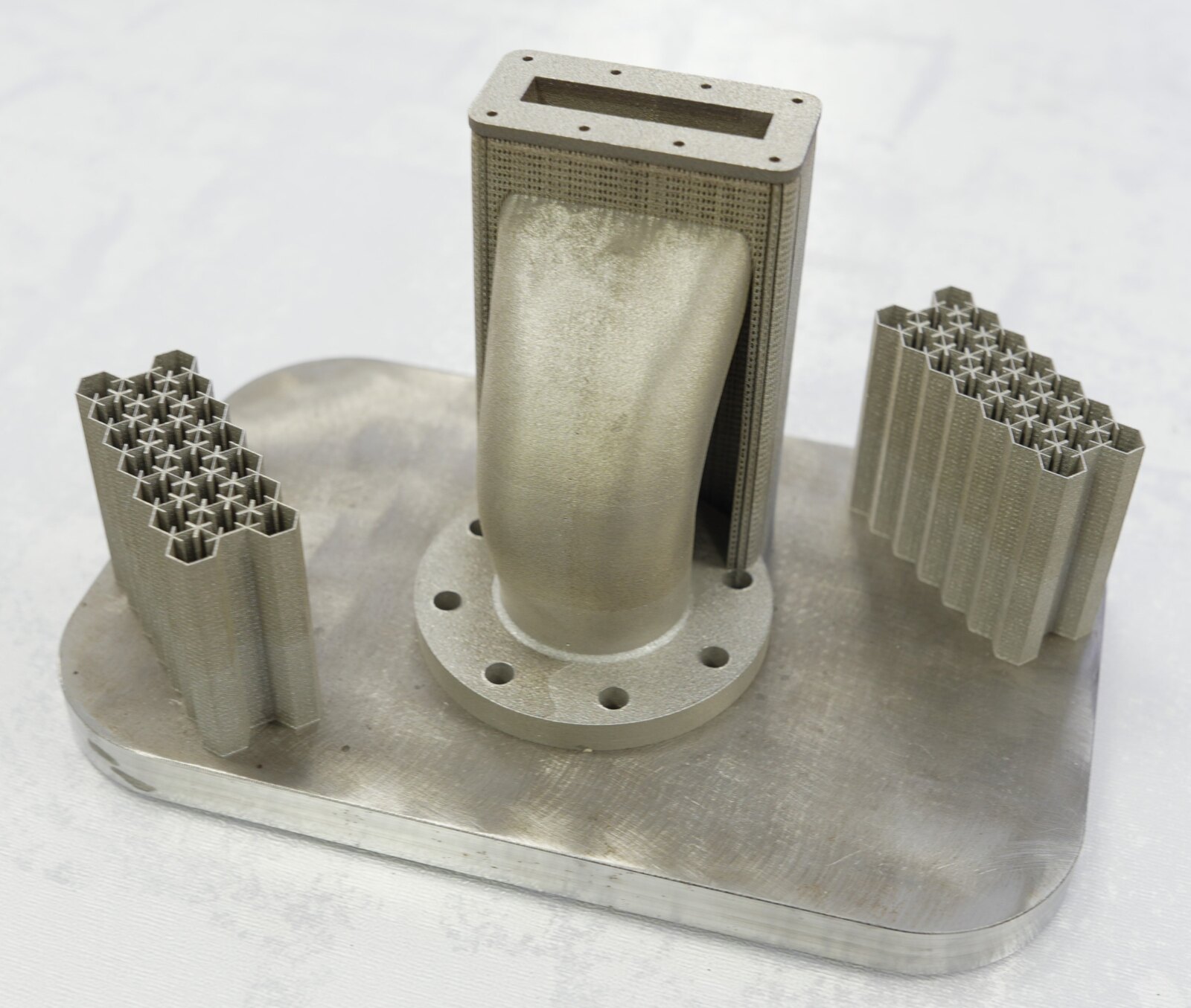
The common way round this is to machine the parts while they are still attached to the build plate. The plate goes onto the machine table or a zero point clamp, and the supports become the fixture. That only works if the supports were designed for it. A support layout drawn purely for printing has done its job once the part is built; under a cutter it has to resist side loads, and thin lattice teeth that were fine for the laser can flex or snap the moment an end mill engages. Under the faces that will be cut we use denser, shorter supports, and on thin parts we check the support layout against the expected cutting load before committing to the build.
Stress relief happens at this stage too. SLM parts carry high residual stress from rapid cooling, and if they are cut off the plate first, they can spring. Heat treating on the plate, then machining, then separating keeps the machined features where they were cut.
Taking the datum from the printer to the machine
The printer and the machining center each have their own coordinate system, and nothing guarantees they agree. The plate may not sit exactly where the CAD file assumed, the part may have grown or shrunk slightly in the build, and on a plate full of small parts each one can be off by a different amount.
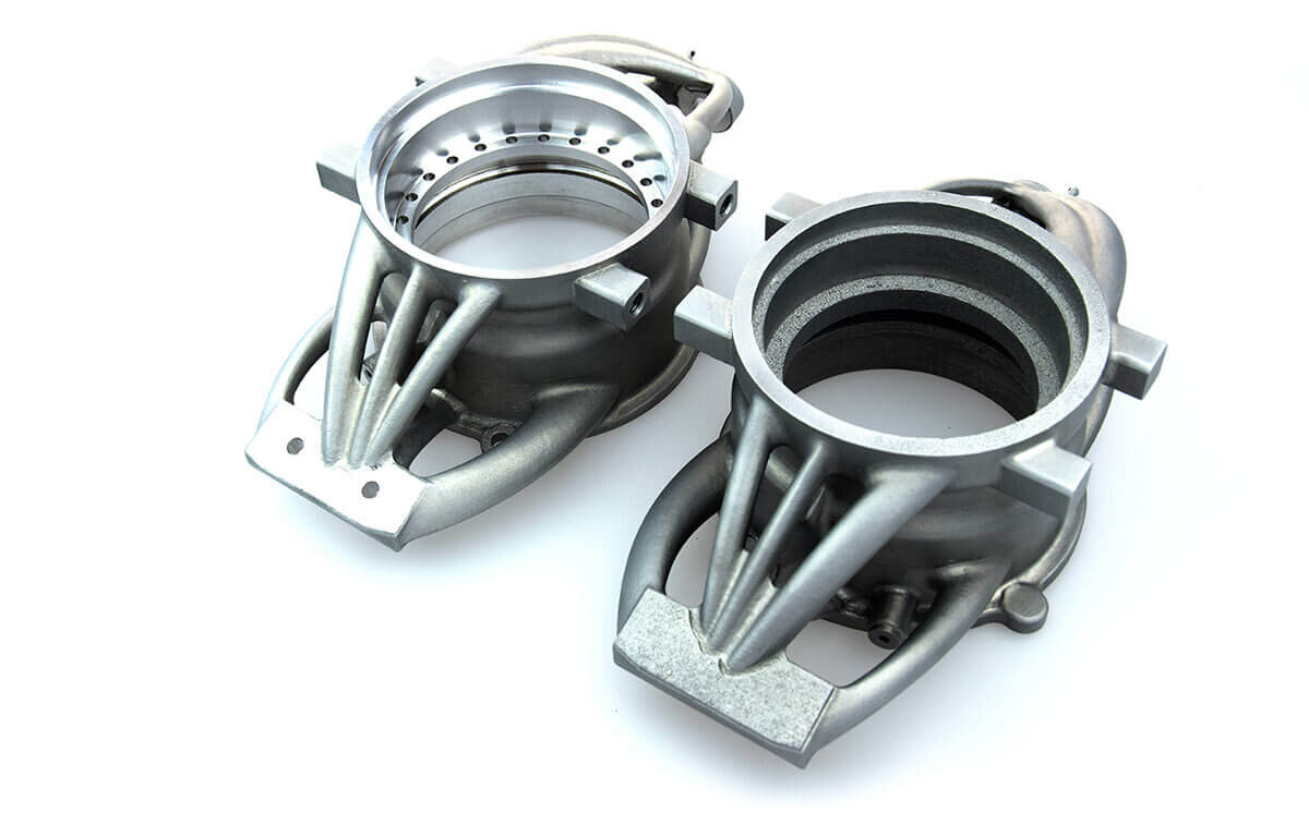
The fix starts in planning. Reference blocks or pads printed on the plate next to the parts give the machine something solid to probe or touch off. From there, a light trial cut on a sacrificial feature shows whether the programmed position matches the real one, and the offset is corrected before any finishing pass touches a functional face.
Plates with many small parts in rows need one more check. The recoater blade can nudge a slender part during the build, so a part that leaned by a fraction of a degree will not line up with the program even when its neighbors do. Probing each part, or at least a sample across the plate, before cutting catches that early, while there is still stock left to correct it.
Cutting forces on a part that is mostly air
Thin walls, narrow necks and lattice sections make small printed parts flexible. Push too hard and the part deflects, the support moves, or the wall chatters, and the result is a bore that measures oval or a slot that is wider at the top. Machining these parts is mostly about keeping the load down.
In practice that means small radial engagement and several light passes instead of one heavy one, sharp tools sized to reach the feature without rubbing on the next one, and a sequence that cuts the datum faces first and the most critical bore or slot last, after the heavier material has already been removed. Support removal comes at the end, with enough clearance that the saw or wire does not mark a finished surface.
A typical route for a printed and machined part
- Drawing reviewSplit the part into printed and machined features, set stock allowances and datums.
- Build preparationChoose orientation, add reference blocks, design supports for printing and cutting.
- Print and stress relieveBuild the parts, then heat treat them while still on the plate.
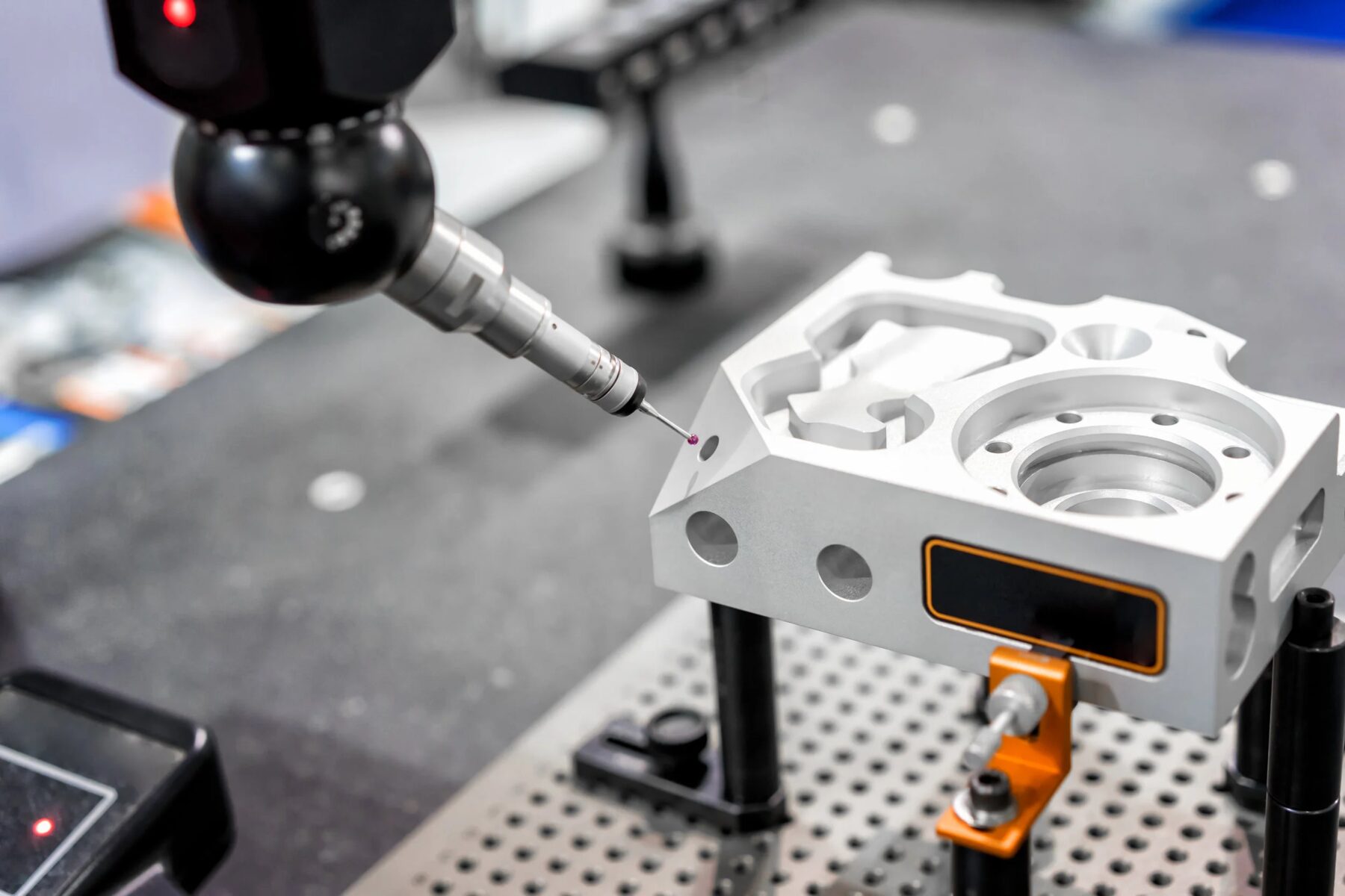
- LocateProbe the reference features, run a trial cut and correct the offsets.
- MachineFinish bores, slots and mating faces with light, controlled passes.
- Separate and inspectRemove supports, finish surfaces and measure the critical features to the drawing.
Not every part needs all six steps. A part with no tight features may only need support removal and blasting.
When printing and machining is the wrong choice
The hybrid route only pays off when the printed shape is worth what the extra planning costs. A bracket that is basically a block with a few pockets and holes is quicker and cheaper machined from solid. At higher quantities, investment casting or metal injection molding usually beats printing on cost per part. And if nearly every surface carries a tight tolerance, printing first only adds a step, because almost everything will be machined anyway.
Where it does make sense is the part with a complex body and a handful of precise interfaces: a compact housing with internal channels, a lightweight bracket with a bearing seat, a manifold with ports that have to seal. That is the combination we look for when a drawing comes in.
Sending a printed and machined part for a quote
A STEP model and a PDF drawing are enough to start. It helps if the drawing marks which faces are machined and which can stay as built, gives the tolerances on those faces, names the material (316L, 17-4PH, Ti-6Al-4V and AlSi10Mg are common choices), and says whether stress relief or HIP is required. If you are not sure where to draw the line between printed and machined features, send the model anyway; an engineer reviews it and comes back with a suggestion before quoting.
More on the printing side is on our metal 3D printing page, and the causes of porosity in SLM parts are covered in this article on part density. For a worked example, see the SLM printed manifold, and for how finished parts are measured, the quality and inspection page. Drawings can be sent through the quote form.
Frequently asked questions
Can SLM printed metal parts be CNC machined?
Yes. Printed parts in 316L, 17-4PH, titanium and aluminum alloys machine much like wrought material once they have been stress relieved. The main differences are the rough as-built skin and the lack of good clamping surfaces on small parts.
How much machining allowance should a printed part have?
On small parts, 0.3 to 0.5 mm on faces that will be cut is a common starting point. Down facing surfaces built over supports and larger parts with more distortion may need more. Holes that will be reamed are printed undersize.
Why machine parts while they are still on the build plate?
Small printed parts often have nothing to clamp. Leaving them on the plate lets the plate act as the fixture, keeps every part in a known position, and avoids making a separate fixture for each one. The supports have to be designed to take the cutting loads.
Should stress relief be done before or after machining?
Before machining, and before the parts are cut off the plate. Removing printed parts without relieving the residual stress first can distort them, and any features already machined would move with them.