ROBOTICS CNC MACHINING · TECHNICAL ARTICLE
Robot Joint Housing Machining: Load Paths, Datums, and Why In-Spec Parts Still Build a Bad Joint
By Martin Ji, TOVILON Precision ·
A robot joint can pass every incoming inspection report and still turn stiff by hand, come up soft on stiffness testing, or feed pose-dependent drift into the torque sensor. When an assembly underperforms despite in-tolerance parts, the defect is usually in how the mating surfaces orient to one another once bolted down.
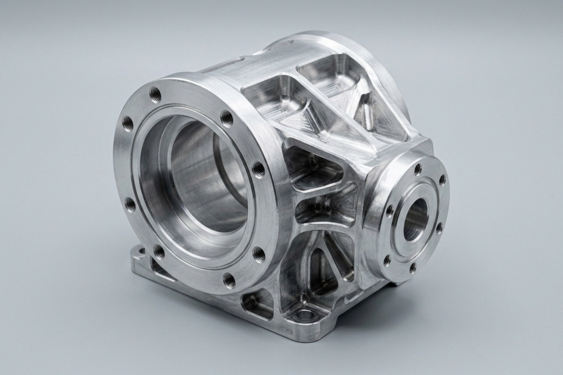
Short answer. A cobot joint housing fixes component alignment and routes structural loads around the torque sensor. Holding individual bore sizes on the print is not enough:
- Control bearing-seat cylindricity, locating-shoulder perpendicularity, and coaxiality to the harmonic reducer pilot against a shared assembly datum.
- Sequence roughing, stress-relief unclamping, and final finishing on deeply pocketed 7075 aluminum links before cutting critical bores.
- Specify whether thin-walled housings are inspected in the free state or restrained against a simulated mating flange so CMM reports match assembly reality.
One joint, multiple load paths
Look at the shoulder joint of a six-axis collaborative robot. Rotating around a horizontal axis, its drive has to lift and accelerate everything outboard—upper arm, elbow, forearm, wrist, end effector, and payload. At the same time, that overhanging mass puts a continuous radial load and overturning moment on the housing, both shifting continuously as the arm moves through its workspace.
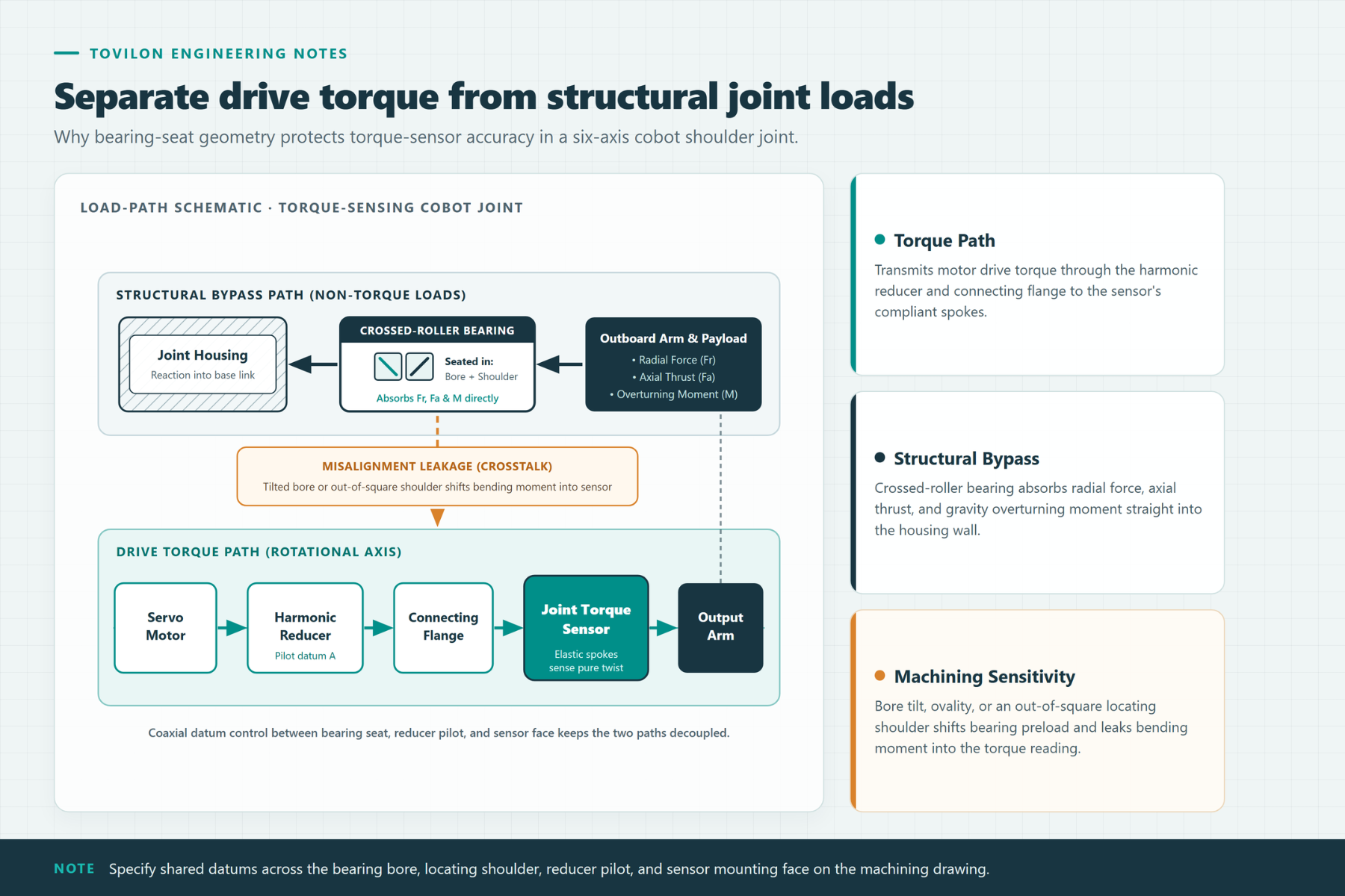
Inside the joint, those loads are supposed to split cleanly. The drivetrain transmits rotational torque about the joint axis; the main bearing absorbs radial force, axial thrust, and tilting moment; the housing anchors both elements and carries reaction forces into the next link.
In a torque-sensing cobot joint, the drivetrain follows a dedicated torque chain: Servo motor → Harmonic reducer → Connecting flange → Joint torque sensor → Output arm. That chain is designed to carry torque, not structural bending. When the arm extends horizontally, gravity generates a high overturning moment at the shoulder. If any meaningful share of that moment leaks through the sensor’s elastic body, the sensing element deforms in ways unrelated to drive torque, and the reading starts drifting with arm posture.
To keep non-torque loads out of the sensor, designers place a crossed-roller bearing between the supporting structure and the output housing so one compact ring absorbs radial, axial, and tilting loads directly. That bypass only works if the bearing seat, connecting flange, and sensor mounting faces land where the CAD model puts them. Shift one interface slightly out of plane or off-axis, and the bearing’s internal contact geometry changes—pushing a fraction of the overturning moment straight back into the sensor.
Where bearing geometry corrupts torque readings
A crossed-roller bearing only performs as well as the machined geometry surrounding it: the seat bore, the locating shoulder, and the clamping flange. Together, those three surfaces establish the bearing’s true rotational axis relative to the reducer and the output link.
Consider a common failure mode. The bearing bore measures round and right on nominal diameter, yet its axis sits slightly tilted relative to the reducer mounting pilot. Checked feature by feature, both pass. Once assembled, the reducer and the bearing try to rotate around two slightly diverging axes. Because neither component is infinitely rigid, the assembly absorbs the mismatch through uneven roller contact, elevated running friction that varies with shaft angle, or angular bind in the connected link.
An out-of-square locating shoulder triggers a related issue. As the clamping flange is torqued down, it rocks the outer bearing ring against the tilted shoulder. Circumferential preload turns uneven, and breakaway torque can shift measurably just by changing the bolt-tightening sequence.
Those mechanical errors show up directly in the electronics. Most joint torque sensors pair an inner hub and outer ring linked by thin elastic spokes that twist slightly under torque to produce a proportional electrical signal. The spokes are engineered to be compliant in torsion and stiff against axial and bending loads—but “stiff” is never infinite. Whenever housing misalignment lets axial thrust or tilting moment bridge into the sensor, part of that parasitic load registers as torque crosstalk.
For the machine shop reviewing the print, this shifts where effort belongs. The tightest diameter callout on the sheet often causes fewer assembly headaches than an uncontrolled relationship between that bore, the shoulder behind it, and the reducer pilot on the opposite face. Identifying which surfaces define the functional rotational axis—and separating them from clearance and cosmetic geometry—should happen before a single toolpath is programmed.
| Symptom on the test bench | Likely housing geometric cause | Drawing & inspection control |
|---|---|---|
| High or angle-dependent friction torque | Bearing bore axis tilted or offset relative to reducer pilot | Coaxiality / total runout of bearing seat to reducer pilot datum |
| Running torque changes with bolt-tightening order | Locating shoulder not square to bore axis; uneven clamping face | Perpendicularity of shoulder to bore axis; clamping flange flatness |
| Pose-dependent torque sensor drift or crosstalk | Misaligned bearing seat or sensor face shunting bending moment into sensor spokes | Shared datum reference frame across bearing bore, shoulder, and sensor face |
| Premature timing-belt wear or tension ripple | Off-axis motor mount center distance error or shaft non-parallelism | True position and parallelism between motor pilot and reducer bore |
Six axes, six completely different housings
The six joints of an articulated cobot share the same basic kinematics, yet their housings face sharply different mechanical trade-offs. The base joint absorbs the full axial weight and overturning moment of the entire manipulator. The shoulder carries peak gravitational torque across the widest range of arm poses. The elbow sees a similar combined load inside a tighter mass and envelope budget, while the wrist axes are governed primarily by compact packaging, low rotational inertia, and dense internal routing.
Most modern cobots route motor power and feedback harnesses internally to keep cables clear of snagging, abrasion, and external interference. That architecture forces hollow reducers, hollow connecting flanges, and clean axial wire passages straight through the rotating structure. When the central axis is reserved for cabling, designers frequently move the motor off-axis and couple it to the reducer through a timing belt.
Moving the motor off-axis introduces a second tier of machining constraints inside the same housing:
- The reducer pilot and bearing seat still require full concentric control.
- The offset motor mount sets pulley center distance and shaft parallelism; small positional errors translate quickly into belt tracking drift, edge wear, or cyclic tension fluctuation.
- The housing wall has to hold that center distance rigid under combined belt preload and arm reaction forces while keeping the central cable tunnel open.
- Internal edges, wire-pass apertures, and adjacent retaining steps require consistent deburring and edge radiusing—a sharp internal lip can wear through harness insulation long before a bearing wears out.
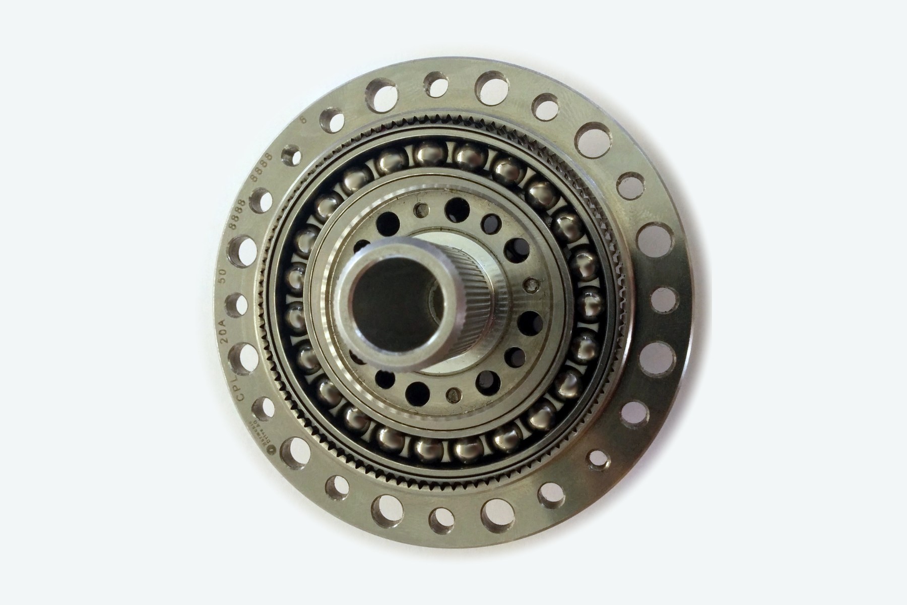
Two housings with the same outer footprint can therefore represent completely different manufacturing jobs. One may be a straightforward turned-and-faced concentric body; the next may combine orthogonal mounting interfaces, deep pockets, offset motor bores, internal wire passages, and thin walls right beside precision bearing seats. Manufacturing difficulty tracks feature-to-feature relationships far more closely than outer dimensions or hole count.

Machining one-piece 7075 aluminum links from solid
Mass reduction pays the biggest dividends furthest from the base. Because rotational inertia scales with the square of distance from the joint axis, a few hundred grams near the wrist penalizes shoulder acceleration and settling time far more than the same mass near the elbow. Designers strip material everywhere it contributes little stiffness while preserving closed load paths between the two end interfaces.
7075 aluminum is a staple alloy for arm links, clevis housings, and structural brackets because of its strength-to-weight ratio. Conventional fusion welding is generally off the table for 7075 due to hot-cracking susceptibility and severe strength loss across the heat-affected zone. Hogging the link or elbow housing out of solid billet eliminates weld distortion and secondary line-boring, and for prototypes or low-to-mid production volumes it avoids die-casting tooling altogether.
Cutting deeply pocketed aluminum links from solid brings a specific set of shop-floor hazards. As thin walls and deep ribs emerge, cutting forces push walls away from the cutter, inviting chatter, taper, and wall-thickness drift. Even stress-relieved plate and bar stock holds internal residual stress gradients: once 75% to 85% of the billet turns into chips, the remaining thin-walled shell can twist or bow the moment clamps release. Meanwhile, the two most critical geometric interfaces—such as a shoulder flange at one end and an elbow bore at the other—often sit across a hollowed-out span with minimal rigid metal connecting them.
- Rough main cavitiesHog out deep pockets and weight-reduction ribs while leaving uniform finishing allowance on critical bores and faces.
- Unclamp & stress-relaxRelease workholding completely so residual stock stresses redistribute before precision finishing begins.
- Re-datum & finishRe-establish primary datums with low-distortion clamping and finish critical end interfaces in minimal five-axis setups.
Five-axis indexing lets the spindle reach opposite faces and angled bores in one clamping to cut out re-fixturing stack-up, though fixturing force, thermal stability, and cut sequencing still decide final geometry.
A featherweight link that springs out of flatness off the fixture—or demands corrective hand-fitting to assemble—erases every benefit of its CAD mass figure.
Building an inspection plan around the assembly
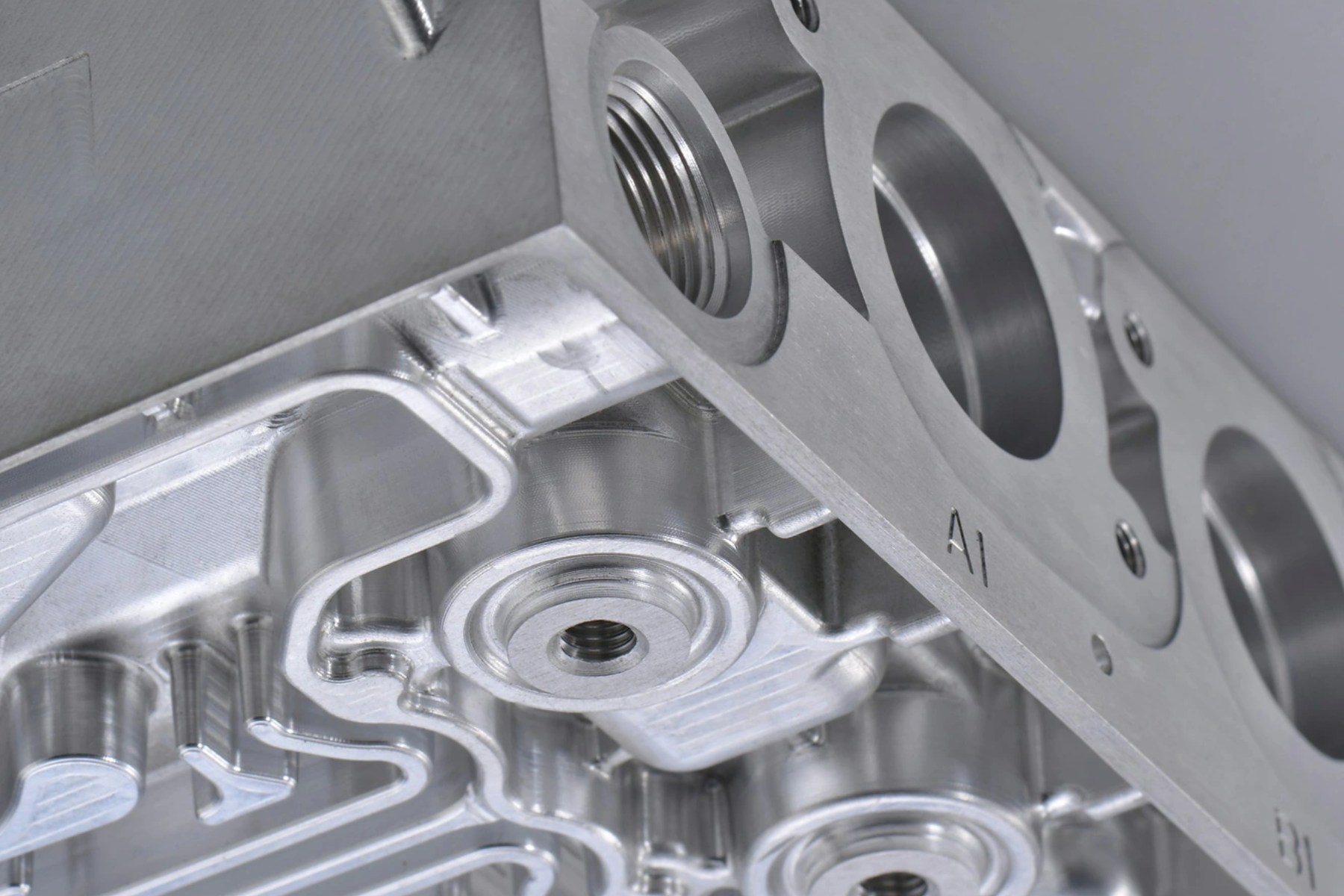
A complex joint housing print can easily carry fifty or more dimensional callouts, yet a handful of geometric relationships dictate how the assembled mechanism behaves: the bearing bore axis, the reducer locating interface, and the output mounting plane.
Take a housing combining a crossed-roller bearing seat with a harmonic reducer mounting face. Bore diameter sets the radial fit; cylindricity governs how uniformly the outer race is supported; the reducer face sets axial position. In the finished joint, what separates smooth motion from premature wear is how those features relate—perpendicularity of the shoulder and mounting face to the bearing axis, true position of the bolt circle, and runout of rotating pilots. Bearing manufacturers’ published housing tolerances provide a sound baseline; tightening every non-functional tolerance on the sheet only adds cycle time and scrap risk without improving joint stiffness or sensor accuracy.
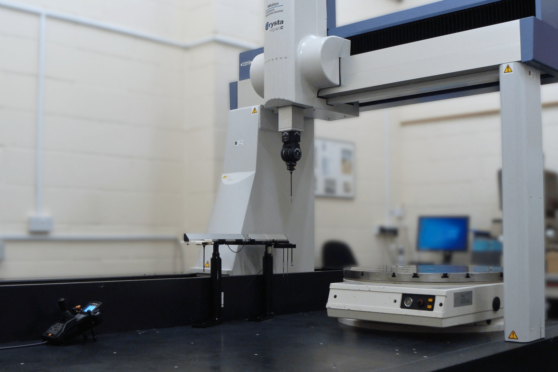
Metrology has to match the geometry being verified. A two-point bore gauge confirms local diameter and nothing more—it will happily pass a tilted bore or a tri-lobed ring. Spatial datum relationships across multiple axes belong on a CMM, while calibrated bore gauges, rotary-table dial indicators, or dedicated functional fixtures remain faster and cleaner for specific single-axis checks.
Just as critical is defining the holding state during measurement. Thin-walled aluminum housings flex measurably under fastener preload. A bore that reads slightly oval in the free state may round up once bolted to a rigid mating flange—or conversely, a housing that passes free-state inspection may distort when torqued onto an uneven face. When a drawing does not specify free versus restrained inspection, supplier and customer metrology reports can disagree on the exact same part.
Finally, component metrology has a clear boundary. Capacitive torque sensors, for instance, measure torque via microscopic changes in electrode gap and capacitance, which means surrounding metallic housing walls subtly alter the local electric field. A sensor calibrated on a bare bench normally needs zero-calibration again after final assembly once the housing and flanges occupy their working positions. Part inspection, mechanical assembly verification, and sensor calibration each catch different failure modes—an in-spec housing is necessary, not a substitute for system-level verification.
What to clarify before releasing joint drawings for quote
When a robotics OEM sends out a joint housing, bearing support, or reducer flange for custom CNC machining, the most productive DFM review resolves four concrete questions before cutting chips:
- Functional surfaces first: Which bores, pilots, and faces directly locate the crossed-roller bearing, harmonic reducer, and torque sensor—and which features are strictly clearance?
- Unified datum hierarchy: Is the bearing seat bore or the reducer pilot the primary datum, and do the CNC setup sheet and CMM inspection routine reference that exact same datum?
- Distortion control: Where do deep pockets or thin walls require an intermediate stress-relief unclamp between roughing and finishing, or dedicated low-force workholding?
- Inspection state: Should critical cylindricity, flatness, and runout callouts be evaluated in the free state or restrained against a simulated mating flange?
Resolving those four points up front puts machining time, fixturing investment, and CMM probing squarely onto the geometry that governs joint stiffness, friction, and torque-sensor accuracy.
TOVILON machines custom components for collaborative robots, humanoid actuators, and industrial automation—including joint housings, bearing supports, reducer mounting flanges, and one-piece aluminum arm links—directly from customer CAD models and 2D drawings. Every quote package is reviewed for alloy selection, thin-wall machining sequence, and assembly-driven datum control before production begins. Explore our CNC machining capabilities, review our quality and CMM inspection process, or send drawings for a manufacturing review.
Frequently asked questions
Why can a robot joint bind or show uneven friction when every housing bore measures in tolerance?
Individual bore size checks do not capture axis tilt, coaxiality offset between the bearing seat and reducer pilot, or an out-of-square locating shoulder. When assembled, those geometric mismatches force the bearing and reducer onto slightly different axes, creating uneven roller preload and angle-dependent friction.
How does housing machining accuracy affect joint torque sensor readings?
Torque sensors rely on compliant spokes to measure twist while staying stiff against bending and axial loads. If bearing seat or mounting face errors disturb the crossed-roller bearing’s contact alignment, a share of the arm’s overturning moment bypasses the bearing into the sensor spokes, showing up as pose-dependent crosstalk.
Why are thin-walled 7075 aluminum robot links machined in separate roughing and finishing stages?
Removing 75% to 85% of a solid aluminum billet releases internal residual stresses in the stock. Unclamping after roughing allows the part to relax before datums are re-established and critical bearing bores and end interfaces are finished, preventing post-machining spring-back.
Should thin-walled joint housings be inspected in the free state or restrained?
It depends on how the housing mounts in the joint. If mating bolt preload pulls a thin flange flat against a rigid structure, restrained inspection better reflects operating geometry; otherwise free-state limits apply. Stating the holding condition explicitly on the drawing avoids conflicting CMM results.